
- Home
- Products
- Company
- Solutions
- Advantages
- Blog
- Contact
- Hot
Views: 0 Author: Site Editor Publish Time: 2026-08-28 Origin: Site


The intermediate drawing phase bridges the gap between heavy rod breakdown and fine wire manufacturing. You need exact mechanical tolerances at this stage. Wire destined for automotive harnesses, residential building circuits, and magnet applications relies entirely on the precision achieved here. When operating an intermediate wire drawing machine, uncontrolled friction, thermal expansion, and inconsistent elongation compound rapidly. These unmanaged factors directly cause wire breaks, surface defects, accelerated die wear, and machine downtime. To produce high-quality wire consistently, operators must master a specific triad of process control. Thermal management, fluid lubrication, and closed-loop tension form the primary evaluation criteria for assessing modern wire drawing equipment. Mastering these three elements ensures continuous production, minimizes scrap, and extends the lifespan of consumable tooling.
Thermal Stability: Modern equipment utilizes targeted capstan and die cooling to manage heat generation (often reaching 150–400°C). While requiring lighter cooling than rod breakdown machines, this precision temperature control prevents metallurgical degradation in thinner wires.
Friction Mitigation: Optimized lubrication systems (spray or bath) are non-negotiable for extending die life and maintaining surface quality across different alloys.
Dynamic Tensioning: Individual AC servo drives, frequency-controlled inverters, and sensor roll controls maintain wire tension within strict ±2% tolerances, eliminating necking and snapping.
System Integration: Successful deployment requires seamless synchronization with downstream components, particularly the continuous inline annealer, to ensure uninterrupted production.
Intermediate wire drawing represents a highly specific stage of diameter reduction on the factory floor. Typically, this equipment takes wire that has already passed through a rod breakdown machine. The wire usually enters the intermediate stage at diameters between 2.5mm and 3.5mm. The machine reduces it further through a series of dies to finishing diameters ranging from 0.4mm to 1.2mm. This stage requires a delicate mechanical balance. The wire is thin enough to snap under improper tension but still thick enough to generate significant frictional heat during draft reduction.
The transition from rod breakdown to intermediate drawing shifts the engineering focus. Rod breakdown machines handle massive mechanical force. They require heavy-duty flood cooling to manage the extreme heat generated by reducing 8mm rod. Intermediate machines utilize light-to-moderate cooling systems. Because the wire is thinner, it generates relatively less absolute heat. However, it demands significantly higher tension precision to prevent stretching or breaking between the drawing capstans.
Drafting schedules dictate the exact area reduction per die, usually ranging from 20% to 26% per draft in intermediate applications. Operators must calculate these reductions accurately to match the motor speeds of the capstans. If the draft schedule does not match the machine's mechanical elongation factor, the wire will either slip excessively on the capstans or pull too tight and break.
Processing variables shift dramatically based on the metal being drawn. When configuring a copper and aluminum wire drawing series, operators must account for distinct metallurgical properties. Aluminum possesses a much lower tensile strength than copper. It requires highly sensitive tension control and specific die geometries to prevent necking. Copper hardens quickly during cold working. It demands aggressive lubrication to maintain surface quality and prevent die scoring.
The output from this stage feeds directly into high-demand manufacturing applications. Intermediate wire serves as the foundation for automotive wiring harnesses, residential building wire, and enameling wire used in electric motors. Understanding these end-uses helps contextualize procurement decisions and return on investment.
When evaluating machine performance, specific success criteria establish the baseline. Overall Equipment Effectiveness (OEE) tracks availability, performance, and quality. Maximum line speed, often measured in meters per second (m/s), dictates throughput. Energy consumption per ton of drawn wire highlights the mechanical and electrical efficiency of the drive systems.
Parameter | Copper Wire Processing | Aluminum Wire Processing |
|---|---|---|
Tensile Strength Handling | High tension tolerance; requires robust capstan grip. | Low tension tolerance; prone to necking and stretching. |
Work Hardening Rate | Rapid hardening; requires immediate downstream annealing. | Moderate hardening; requires specialized die angles. |
Lubrication Requirement | Fat-rich emulsions (4-7% concentration). | High-viscosity oils or specific synthetic emulsions. |
Die Geometry (Approach Angle) | Standard approach angles (16-18 degrees). | Wider approach angles to accommodate softer metal flow. |
Wire drawing is a process of severe plastic deformation. As the wire pulls through the reducing geometry of the die, mechanical work and intense surface friction generate massive thermal loads. Temperatures at the die interface routinely reach 150–400°C. If left unchecked, this heat transfers into the wire. It alters the grain structure and degrades the mechanical properties of the metal, making it unsuitable for downstream processing.
To combat this, manufacturers engineer narrow-gap water cooling systems inside the drawing capstans. These internal systems circulate chilled water just beneath the surface of the capstan drum. The narrow gap increases the velocity of the cooling water. This maximizes heat transfer away from the wire. Rotary joints connect the stationary water supply lines to the spinning capstans, maintaining consistent flow rates. The goal is to stabilize the capstan surface temperature without over-chilling the wire. Over-chilling can make the metal brittle before it enters the next draft.
Direct die cooling addresses heat at the source. Coolant circulates directly around the exterior casings of the drawing dies. This prevents the thermal expansion of the tungsten carbide or Polycrystalline Diamond (PCD) die inserts. If a die expands, the wire diameter drifts out of tolerance. Direct cooling locks the die geometry in place. It ensures consistent wire gauge from the start of the run to the finish.
Plant infrastructure plays a major role in thermal management. The machine's internal heat exchangers—typically plate or shell-and-tube designs—must integrate seamlessly with the facility's central cooling tower. If the central cooling tower cannot supply water at the correct entry temperature (usually around 25-30°C), the machine's internal cooling efficiency drops, leading to overheated capstans and wire breaks.
Implementing these cooling architectures introduces specific maintenance risks. Hard water causes scaling and mineral buildup inside the narrow cooling channels. Over time, this buildup restricts flow and insulates the capstan, drastically reducing cooling efficiency. When evaluating equipment, you must assess preventative maintenance accessibility. Operators need clear access to flush cooling lines, inspect rotary joints, and replace seals without dismantling the entire drive assembly.
To maintain optimal thermal stability, maintenance teams should follow a strict cooling system protocol:
Inspect rotary joints weekly for slow leaks or pressure drops.
Test cooling water hardness monthly to prevent calcium scaling inside capstan jackets.
Flush the narrow-gap cooling channels with a descaling solution every six months.
Verify the flow rate at the die cooling manifolds using inline flow meters.
Calibrate the heat exchanger thermostats to ensure the supply water remains at the specified entry temperature.
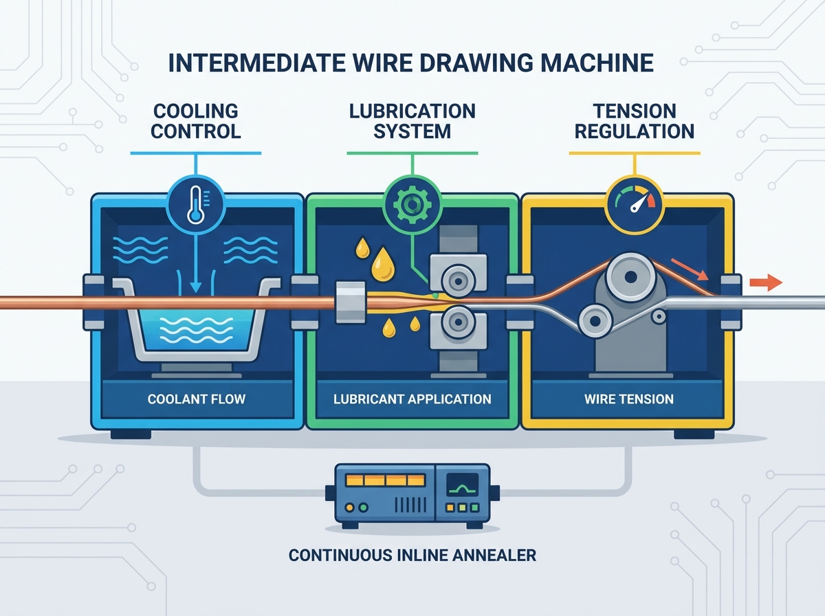
Lubrication serves two primary functions in wire drawing. It reduces friction between the wire and the die, and it flushes away metallic fines. Equipment manufacturers typically deploy one of two fluid delivery methods: full submersion bath systems or directed spray systems.
Bath systems submerge the entire drawing zone—capstans, dies, and wire—in a continuous pool of emulsion. This provides excellent cooling and guarantees fluid coverage. However, it requires a massive volume of lubricant and heavy-duty filtration. Directed spray systems use targeted nozzles to inject lubricant directly into the die entry and onto the capstan surface. Spray systems use less fluid volume and offer high cooling efficiency. They require precise nozzle alignment. If a nozzle clogs, the die runs dry and fails almost instantly.
System Type | Fluid Volume Required | Cooling Efficiency | Filtration Demand | Maintenance Focus |
|---|---|---|---|---|
Full Submersion (Bath) | High (Hundreds of gallons) | Excellent (Bulk Heat Removal) | High (Large particulate load) | Tank cleaning, bulk fluid changes, sludge removal |
Directed Spray | Low to Medium | High (Targeted Heat Removal) | Moderate | Nozzle alignment, clearing clogs, pump pressure checks |
Managing fluid chemistry dictates operational success. You must monitor emulsion concentrations, pH levels, and temperatures daily. When switching between metals, fluid management becomes even more demanding. Copper emulsions typically run at different fat concentrations and pH levels than aluminum lubricants. Using the wrong viscosity or chemistry leads to fluid breakdown, increased friction, and severe die wear.
Tramp oil contamination presents a major threat to emulsion stability. Hydraulic oils or gear lubricants leaking from the machine's drive section can mix with the drawing emulsion. This tramp oil coats the wire, preventing the actual drawing lubricant from doing its job. It also promotes bacterial growth in the fluid tank, which degrades the emulsion and causes foul odors on the plant floor. Regular skimming and maintenance of drive seals prevent this contamination.
Lubrication efficiency links directly to surface finish outcomes. As wire draws through the die, microscopic pieces of metal shear off. This creates metallic dust or fines. A robust lubrication system flushes these fines out of the die throat. If fines accumulate, they score the wire surface. This creates scratches that cause the wire to fail electrical testing downstream.
Integrated fluid management systems handle filtration and recirculation. Paper bed filters, magnetic separators, or centrifuge systems remove particulate matter from the dirty emulsion. Effectively removing these fines extends the lifecycle of the drawing lubricant. It reduces hazardous waste disposal and ensures only clean fluid returns to the drawing zone.
Multi-draft elongation relies on precise speed synchronization. As wire passes through each successive die, its cross-sectional area decreases, and its length increases. To prevent the wire from bunching up or snapping, the speed of each subsequent capstan must increase exponentially to match this elongation. Managing this speed differential requires exact tension control.
Sensor rolls and dancer arms provide physical tension feedback. A dancer arm is a weighted or pneumatically loaded pulley that rides on the wire between drawing stages or before the take-up spool. If the wire tension drops, the arm falls. If the tension spikes, the arm rises. A potentiometer or linear transducer reads this physical movement and sends a real-time electrical signal to the machine's control system.
Computer drawing systems and frequency-controlled drives (VFDs) process these feedback signals using a Proportional-Integral-Derivative (PID) control loop. The computerized system automates draft calculations based on the specific die string loaded into the machine. The PID loop adjusts the tension profiles on the fly, speeding up or slowing down individual drives to keep the dancer arm in its neutral center position. If the PID loop is tuned poorly, the dancer arm will oscillate wildly, causing the wire to stretch and snap.
Modern equipment has largely shifted away from single-motor mechanical slip machines. Instead, individual AC servo drives power each capstan. This architecture provides closed-loop control, typically holding wire tension within a strict ±2% tolerance. Individual drives eliminate mechanical slip, reduce capstan wear, and allow operators to draw sensitive alloys without risking necking or breakage.
Despite advanced electronic controls, physical safety mechanisms remain necessary. Rapid-response pneumatic braking systems handle emergency stops. If a wire breaks or a safety guard opens, the pneumatic brakes engage instantly. They halt the spinning capstans in fractions of a second. This prevents thousands of feet of loose wire from tangling inside the machine and ensures operator safety.
Operators must follow specific procedures to calibrate tension systems during a changeover:
Verify the pneumatic pressure supplied to the dancer arm cylinders matches the recipe requirements for the specific wire gauge.
String the wire through the die sequence and manually jog the drives to establish initial tension.
Check the linear transducer feedback on the HMI to ensure the dancer arm registers exactly at the zero-point center.
Run the machine at 10% line speed to observe the dancer arm stability before ramping up to full production speed.
Adjust the PID loop tuning parameters in the PLC if the dancer arm oscillates or hunts during acceleration.
Cold working hardens the metal. By the time the wire exits the final drawing capstan, it is brittle and stiff. To restore its conductivity and flexibility for downstream stranding or extrusion, the wire must be annealed. The handoff protocol between the drawing machine and the annealing unit is a major transition point on the factory floor.
The work-hardened wire leaves the drawing section and immediately enters the continuous inline annealer. This integration requires flawless speed and tension matching. The drawing machine's master programmable logic controller (PLC) synchronizes the final capstan drive speeds with the annealer's contact pulleys.
If the speeds mismatch even slightly, the results are immediate. Too much slack causes the wire to lose contact with the electrified annealing pulleys. This results in heavy arcing and sparking that pits the wire surface and damages the pulley bands. Too much tension stretches the heated, softened wire, altering its final diameter or snapping it entirely.
Thermal preparation also plays a role in this handoff. The residual heat left in the wire as it exits the drawing machine impacts the electrical efficiency of the annealing process. Wire that enters the annealer pre-warmed requires slightly less electrical current to reach its full annealing temperature. This optimizes energy usage across the entire line and reduces the thermal shock on the metal.
Selecting the right equipment requires mapping specific machine features to your desired production outcomes. A features-to-outcomes matrix helps clarify these decisions. Choosing a multi-motor AC servo drive system over a traditional dual-motor setup directly results in reduced wire slip, longer capstan life, and measurable energy savings. You must align the hardware specifications with your daily production hurdles.
Scalability and automation dictate how well the machine handles high-mix production environments. Facilities running multiple wire gauges or switching between alloys benefit heavily from automated die-stringing aids and quick-change die holders. Digital HMI/SCADA systems allow operators to save specific tension and speed recipes. Instead of manually tuning the machine for an hour, the operator selects the recipe, and the PLC automatically configures the drives for the new product run.
Data logging capabilities represent a major evaluation dimension for modern facilities. Machines equipped with OPC UA communication protocols can push real-time production data to the plant's central ERP system. This allows engineering teams to track OEE, monitor scrap rates, and predict maintenance intervals based on actual motor loads rather than calendar days.
Long-term operational efficiency factors determine the true value of the equipment. You must calculate ongoing consumable costs. Evaluate the expected die replacement rates based on the machine's cooling and lubrication efficiency. Track the projected lubricant consumption and the energy efficiency of the drive motors. Assess the availability of spare parts for proprietary servo drives and PLCs. A machine that saves energy but requires custom, hard-to-source electronics will cause severe downtime during a component failure.
An intermediate wire drawing machine's viability rests entirely on its ability to balance thermal loads, fluid dynamics, and mechanical tension simultaneously. Failing to control heat degrades the wire. Poor lubrication destroys dies. Inaccurate tension snaps the product. Success requires integrating all three systems into a cohesive, automated platform.
When shortlisting equipment, procurement and engineering teams must prioritize transparency. Look for vendors who provide clear, documented data on servo response times, cooling flow rates, and integration capabilities with existing annealing equipment. Avoid machines with closed-architecture software that prevents you from tuning tension profiles.
To move forward with upgrading or installing new drawing capacity, take the following actions:
Initiate technical consultations with OEMs to request specific case studies on die life extension for your exact alloys.
Require vendors to provide tension tolerance data and dancer arm response times under maximum line speed conditions.
Audit your current facility's water hardness and filtration capabilities to ensure compatibility with modern narrow-gap cooling systems.
Map out the exact PLC communication protocols required to sync a new drawing machine with your existing downstream annealers and spoolers.
A: A rod breakdown machine handles heavy, thick wire rod using massive mechanical force and heavy flood cooling. An intermediate machine takes the output from the breakdown stage and draws it down to finer diameters. Intermediate machines use lighter cooling but require significantly higher precision in tension control to prevent the thinner wire from breaking.
A: It prevents breakage using closed-loop tension control. Dancer arms or sensor rolls physically detect slack or tightness in the wire. They send real-time signals to frequency-controlled AC servo drives, which instantly adjust the speed of individual capstans to maintain tension within a strict ±2% tolerance, preventing stretching or snapping.
A: The best lubrication depends on the metal. Copper typically requires rich, fat-based emulsions to handle work hardening and maintain surface finish. Aluminum requires distinct lubricants with different viscosities and pH levels to prevent the softer metal from galling or sticking to the dies. Dual-metal machines must have separate fluid management systems.
A: Capstan cooling removes the bulk of the frictional heat generated during the drawing process. If capstans run hot, that heat transfers down the wire and into the next die. Excessive heat causes tungsten carbide or PCD dies to thermally expand, altering the wire diameter and accelerating the physical wear of the die throat.
A: Synchronization is achieved through a master PLC that networks the drawing machine's final capstan drive with the annealer's contact pulleys. The PLC constantly monitors wire speed and adjusts the drives to maintain perfect tension. This prevents the wire from sagging and losing electrical contact or pulling too tight and stretching.
A: Due to severe plastic deformation and mechanical friction, temperatures at the die interface typically range between 150°C and 400°C. Effective direct die cooling and robust fluid lubrication are required to manage this heat and prevent metallurgical damage to the wire.


 English
 简体中文
简体中文
