
- Home
- Products
- Company
- Solutions
- Advantages
- Blog
- Contact
- Hot
Views: 0 Author: Site Editor Publish Time: 2026-05-12 Origin: Site


The global wire drawing market is accelerating fast. Industry forecasts project a 7.5% compound annual growth rate over the next decade. Operational pressures continue mounting for manufacturers globally. Facilities face volatile energy prices, strict ASTM quality standards, and a severe shortage of skilled machine operators. Managing these compounding challenges requires strategic equipment upgrades.
Keeping up with trends in copper wire manufacturing is no longer about chasing shiny novelties. It focuses strictly on mitigating operational risk. Modernizing your equipment helps reduce scrap rates dramatically. It also future-proofs production lines against rapidly rising costs. Relying on outdated machinery drains profitability through excessive downtime and material waste.
This article provides plant managers and procurement engineers with a pragmatic, evidence-based framework. It will help you evaluate a modern copper wire drawing machine based on current technological advancements. You will learn how automation bridges the labor gap, how die engineering defines production yield, and why inline thermal processing remains vital for energy reduction.
Automation solves the labor gap: Advanced PLC and IoT integrations enable predictive maintenance and reduce reliance on highly experienced operators.
Die engineering defines yield: Optimized multi-pass systems (e.g., specific die angles and tension controls) prevent necking and fracture even at 99%+ cross-section reductions.
Inline processing cuts energy costs: Integrated continuous annealing (350–650°C) eliminates the need for secondary batch heat treatments.
Modularity dictates ROI: Modern equipment must offer rapid die-change capabilities to seamlessly shift from rod breakdown to fine wire production (down to 0.03mm) based on market demands.
Legacy wire manufacturing equipment hides numerous operational costs. Older systems suffer from frequent wire breaks during high-speed runs. These breaks halt production and force operators to manually re-thread the entire line. This process wastes valuable time. High scrap rates directly erode raw material margins. Furthermore, reactive maintenance schedules disrupt delivery timelines. Outdated drive motors and inefficient lubrication systems consume excessive electrical power. These hidden drains destroy profit margins in an era of volatile energy pricing.
We must also look at downstream market drivers. Global electrification demands push manufacturers toward higher standards. Electric vehicles (EVs) require high-purity, defect-free copper components. Superconductor applications demand wiring without surface micro-fractures. Downstream clients will reject spools showing even minor gauge variations. Your equipment must meet these strict tolerance requirements consistently.
You need specific success criteria for any new machinery investment. A proper upgrade must measurably improve energy efficiency across the factory floor. It must expand production flexibility so you can handle multiple wire gauges on a single shift. Upgraded machinery must also ensure strict compliance with standard testing. Quality control departments evaluate diameter, ovality, surface finish, and electrical resistance. Your new production line must automate and stabilize these exact metrics.
Common Mistake: Many procurement teams focus solely on the initial capital outlay. They ignore the daily scrap costs generated by outdated tension control mechanisms. Always calculate the monthly cost of wasted copper when evaluating the need for an upgrade.
Moving from reactive to predictive maintenance changes everything about plant operations. You no longer wait for a bearing to fail. IoT sensors and machine learning algorithms monitor operations continuously. These digital tools track real-time capstan friction. They measure lubricant temperature variations and detect microscopic vibration anomalies. By analyzing this data, the system predicts bearing or die failures long before downtime occurs. Operators can schedule part replacements during planned shift changes.
Advanced control systems remain crucial for overcoming the labor shortage. Sophisticated Programmable Logic Controller (PLC) systems govern modern machines. Human-Machine Interface (HMI) screens provide intuitive visual feedback. These systems automate tension and speed adjustments dynamically. They drastically reduce the learning curve for new operators. Instead of relying on a veteran operator’s intuition, the machine self-corrects based on programmed recipes.
Implementation reality matters heavily during the procurement phase. Buyers should rigorously verify software compatibility. The manufacturer's proprietary software must integrate smoothly into existing plant ERP or MES systems. Operating a digital machine in an isolated silo defeats the purpose of Industry 4.0 integration.
Follow these implementation steps when integrating digital drawing systems:
Audit your existing factory network infrastructure for bandwidth capacity.
Request OPC-UA communication protocols from the machine vendor to ensure compatibility.
Establish baseline metrics for vibration and temperature during the first week of operation.
Train maintenance staff to interpret software alerts rather than relying solely on physical inspections.
The physics of wire drawing dictates your final yield. Multi-pass cold drawing involves intense mechanical stress. As copper passes through consecutive dies, it undergoes strain hardening. The copper becomes progressively harder and more brittle. The core engineering challenge is straightforward. You must keep tensile stress at the die exit strictly below the material's yield stress. Achieving this balance prevents necking and catastrophic fracture.
Engineering benchmarks provide proven optimization parameters for this process. Industry standards strongly favor the adoption of 9° die half-angles for standard copper drawing. Precise bearing length ratios also play a key role. A bearing length set to 25% of the final diameter stabilizes the wire perfectly. These specific parameters allow continuous processing from large 8mm rods down to fine gauges. They achieve these massive cross-section reductions without requiring intermediate annealing steps.
Friction management directly impacts speed and final surface quality. Modern payoff systems manage back-tension effectively before the wire even enters the first die. Capstan designs utilize specialized coatings to control friction coefficients. They ensure uniform wire stress across the entire draft sequence. This stability holds true even across extreme high-speed runs reaching up to 2000 meters per minute.
The table below outlines common friction management variables and their impact on production:
Friction Variable | Optimal Condition | Impact on Wire Quality |
|---|---|---|
Capstan Surface Roughness | Tungsten carbide coated, polished | Prevents micro-scratching on the copper surface. |
Lubricant Temperature | Maintained between 35°C and 45°C | Ensures stable viscosity for continuous die cooling. |
Payoff Back-Tension | Constant, automated pneumatic control | Prevents wire sagging and sudden tension spikes at entry. |
Die Alignment | Strictly perpendicular to the drawing axis | Eliminates ovality defects and uneven bearing wear. |
Best Practice: Always implement a strict die inspection routine. Use laser measurement tools to check die angles and bearing wear after every high-volume production run. Discard dies falling out of the 9° half-angle tolerance.
Combining process steps streamlines the factory floor significantly. Traditional batch annealing requires separate handling. Operators move heavy spools into massive bell furnaces, baking them for hours. Continuous inline annealing changes this dynamic entirely. The wire passes directly through a controlled thermal zone immediately after the final draw. This electrical contact zone typically heats the wire between 350–650°C. This instant thermal shock restores the copper's ductility in real-time.
Cost and footprint reduction become immediately apparent. Inline setups reduce the physical factory footprint by eliminating giant holding furnaces. They minimize work-in-progress (WIP) inventory significantly. You no longer have hundreds of spools sitting idle waiting for heat treatment. This consolidated process also lowers overall energy consumption, as you only heat the exact volume of moving wire rather than an entire furnace chamber.
Cooling system criticality cannot be overstated in these continuous setups. Advanced cooling and lubrication systems are mandatory. They must dissipate the massive heat generated by both mechanical friction and electrical annealing. Proper cooling prevents oxidation on the wire surface. It also extends the lifespan of expensive carbide and polycrystalline diamond (PCD) dies.
Consider the following comparison chart detailing the shift from batch to inline methods:
Process Comparison Chart: Thermal Treatments | ||
|---|---|---|
Metric | Traditional Batch Annealing | Continuous Inline Annealing |
Processing Time | 4 to 8 hours per batch | Seconds (Real-time integration) |
Floor Space | High (Requires large bell furnaces and staging areas) | Low (Integrated directly into the drawing machine) |
Energy Waste | High (Heating entire furnace atmosphere and spool mass) | Low (Direct joule heating of the wire only) |
Surface Oxidation Risk | Moderate (Depends on vacuum or inert gas seals) | Low (Immediate liquid quenching prevents oxygen exposure) |
Categorizing equipment by specific production needs helps narrow your options quickly. Manufacturers engineer different machines for distinct stages of the wire reduction lifecycle.
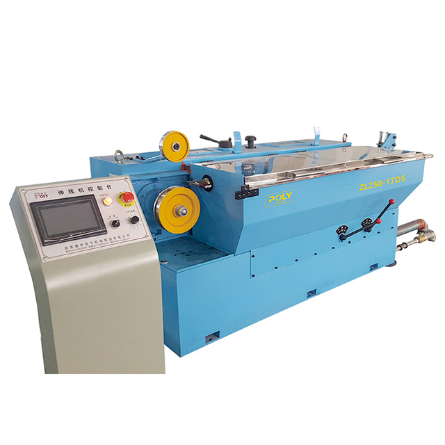
Rod Breakdown Machines (RBD): These machines handle the heavy-duty reduction of 8.0mm continuous cast rods. Look for equipment featuring independent motor drives for each capstan. This design minimizes slip. Ensure robust payoff integration to handle massive rod coils safely.
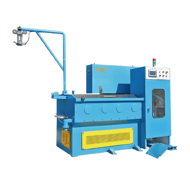
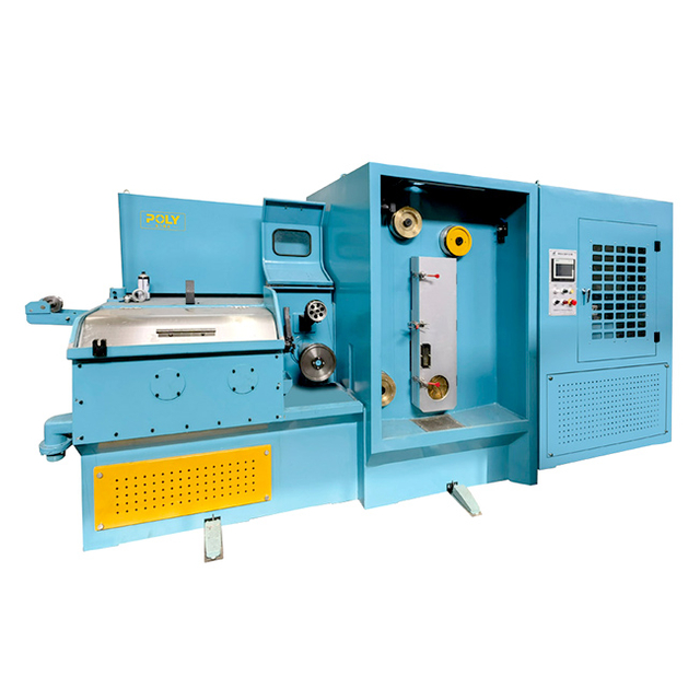
Intermediate and Fine Wire Machines: These units serve the electronics and telecom sectors. They must support rapid die changes to accommodate shifting daily orders. They require extreme precision, drawing wire down to 0.01mm–0.03mm diameters. Tension control here relies on highly sensitive dancer arms.
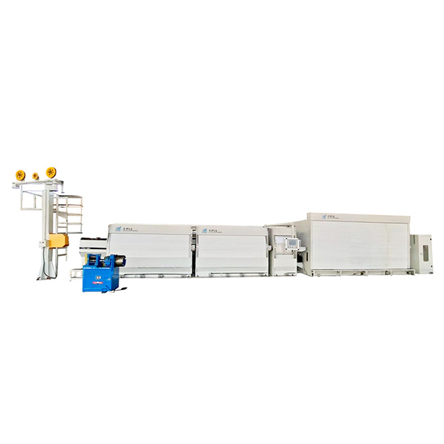
Multi-Wire Systems: These target high-volume construction or automotive wire manufacturing. A multi-wire line might pull 8, 16, or even 24 wires simultaneously. Evaluate simultaneous multi-line tension stability carefully. A single broken wire in a multi-line setup ruins the efficiency of the entire run.
Scalability versus specialization requires a strategic business choice. Buyers must decide between highly specialized single-line high-speed machines and flexible multi-purpose lines. Analyze your historical order variability. If your facility produces a high mix of different gauges, prioritize rapid die-change systems and flexible HMI recipes. If you produce massive volumes of a single gauge, prioritize raw speed and dedicated cooling infrastructure.
Vendor support and parts availability ultimately secure your long-term investment. Equipment lifecycle value depends heavily on reliable aftermarket support. You need rapid access to wear parts like specialized dies, contact bands, and coated capstans. Technician training programs are equally important. Without proper operator training, even the most advanced machine will underperform. For specific configuration inquiries or to discuss tailored technician training programs, you can contact us directly.
Keeping up with copper wire drawing trends requires a strategic mindset. Adopting modern automation and advanced die engineering maximizes production yield significantly. These technologies minimize human error across the factory floor. Ultimately, upgrading your equipment lowers per-meter production costs and protects your competitive edge.
Decision-makers must take actionable next steps. Audit your current scrap rates and electrical energy usage immediately. Identify exactly where legacy machines bleed profit. When shortlisting machine manufacturers, request specific cycle-time data and tension-control case studies. Demand proof of seamless ERP integration. Upgrading your infrastructure today ensures compliance with tomorrow's strict industry standards.
A: Wire breakage is typically caused by improper die angles, inadequate lubrication leading to excessive friction, or incorrect tension control resulting in tensile stress exceeding the copper's yield strength (necking).
A: Rod Breakdown (RBD) machines take raw 8mm cast copper rods and reduce them to intermediate sizes (e.g., 2mm), requiring massive torque and independent motors. Fine wire machines take intermediate wires and draw them down to micro-diameters (below 0.1mm) at extremely high speeds, requiring delicate tension control.
A: It eliminates the need to transport hardened wire to a separate batch furnace. By electrically heating the wire to 350–650°C directly on the drawing line, it instantly restores ductility, saving energy, time, and floor space.
A: High-quality machinery ensures compliance with key ASTM specifications regarding final diameter tolerances, ovality limits, surface finish quality, tensile strength, elongation, and electrical resistance.

 English
 简体中文
简体中文

