
- Home
- Products
- Company
- Solutions
- Advantages
- Blog
- Contact
- Hot
Views: 0 Author: Site Editor Publish Time: 2026-05-20 Origin: Site


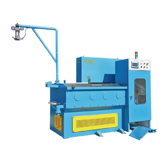
For wire and cable manufacturers, output quality defines business survival. Copper wire quality directly dictates downstream yield, electrical compliance, and brand reputation. Substandard drawing processes cause unacceptable scrap rates. They accelerate tooling wear and introduce catastrophic short-circuit risks in end-use applications. Evaluating equipment requires looking far past raw production speed. True operational success relies on hitting stringent dimensional thresholds consistently. It requires achieving mechanical and electrical targets without constant operator intervention. This article breaks down the definitive quality metrics for drawn copper wire. We will explore the core engineering parameters causing hidden defects. Finally, you will learn how to evaluate a copper wire drawing machine based on its capability to control these critical variables.
Comprehensive wire quality is defined by five pillars: diameter tolerance, surface integrity, electrical conductivity, tensile strength, and chemical purity.
High-performance drawing machines rely on precision die geometries (6–15° angles) and advanced continuous inline annealing (350°C–650°C) to prevent material hardening.
Process control—specifically managing emulsion temperatures (35°C–45°C) and understanding friction speed thresholds (around 15 m/s)—is critical for extending die life and maintaining surface quality.
Equipment shortlisting should prioritize machines with integrated PLC tension control, automated fluid management, and synchronized multi-stage breakdown capabilities.
Minor deviations in wire quality compound rapidly. They destroy margins across your entire production floor. We see this impact clearly across three major operational areas.
Drawn wire rarely serves as the final product. It moves downstream into extrusion, stranding, or enameling processes. Bumpy or inconsistent copper wire creates immense downstream headaches. An inconsistent wire diameter forces the extrusion machine to apply uneven insulation. You waste expensive polymer materials trying to cover the faults. Ultimately, these minor drawing deviations create massive scrap volumes. High scrap rates directly choke your manufacturing profitability.
Poor diameter consistency alters the electrical resistance of your wire. Thinner sections create localized heating during power transmission. This heating degrades insulation over time. Consequently, your product fails stringent industry standards like ASTM and IEC. Non-compliance often triggers catastrophic product recalls. Your brand reputation suffers severe damage when cables fail in the field.
Poor input wire quality acts like abrasive sandpaper inside your equipment. Improper machine setup forces metal through dies incorrectly. This creates extreme friction and heat. Premature die wear becomes inevitable. You find yourself replacing expensive diamond or tungsten carbide dies constantly. Increased maintenance operations cripple your production schedule. Mastering your drawing variables prevents this aggressive tooling depreciation.
You cannot improve what you cannot measure. Manufacturers must implement authoritative testing frameworks. We judge copper wire quality across five non-negotiable pillars.
Quality Metric | Industry Standard | Testing Method | Production Impact |
|---|---|---|---|
Diameter Tolerance | Tolerances as tight as ±0.001mm | Multi-point micrometer or inline laser | Inconsistent resistance, connector mismatch |
Surface Quality | Smooth, zero micro-cracks or pitting | Visual inspection, profilometers | Traps contaminants, high secondary friction |
Electrical Conductivity | 100% IACS benchmark | Four-point probe (V=IR calculation) | Indicates work hardening or impurities |
Tensile Strength | Balanced yield vs. elongation | Universal tensile testing machine | Defines survivability during flexing |
Chemical Purity | Minimum 99.9% copper (ETP/OFE) | OES or XRF spectroscopy | Degrades ductility and conductivity |
High-precision electrical applications demand absolute dimensional perfection. Acceptable tolerances often reach as tight as ±0.001mm. You must utilize multi-point micrometer checks to verify these dimensions. For continuous production, inline laser micrometers provide superior real-time data. Deviations here directly cause inconsistent electrical resistance. Furthermore, mismatched diameters prevent secure physical connections in terminal blocks.
A flawless wire surface appears smooth and highly reflective. It must remain free of micro-cracks, scratches, or pitting. You can use visual inspection to catch gross defects. However, true quality control requires profilometers for microscopic roughness analysis. Rough surfaces ruin subsequent processing. They increase friction during secondary drawing stages. Furthermore, pits trap chemical contaminants and drastically reduce the wire's corrosion resistance.
Conductivity defines the fundamental purpose of copper wire. You must benchmark your product against 100% IACS (International Annealed Copper Standard). Engineers measure this using the four-point probe method. This test calculates conductivity via Ohm’s law. Poor conductivity reveals deep process failures. It usually points to improper inline annealing, severe work hardening, or trace impurity introduction.
Mechanical survivability requires a delicate balance. You must balance yield strength against elongation. High yield strength prevents breakage under heavy loads. Excellent elongation allows the wire to bend without fracturing. Universal tensile testing machines evaluate these properties accurately. This metric defines the wire's survivability during harsh installation environments and dynamic flexing applications.
The raw material heavily dictates the final output. The standard requires a minimum of 99.9% copper purity. Manufacturers typically use ETP or OFE copper grades. You can verify composition using Optical Emission Spectroscopy (OES) or X-ray Fluorescence (XRF). Trace impurities like sulfur, iron, or oxygen are fatal. They degrade both mechanical ductility and electrical performance simultaneously.
Quality metrics tie directly back to the physical capabilities of your equipment. Understanding these components aids greatly in technical evaluation.
The drawing die forces the copper into its new shape. Utilizing proper die angles ensures uniform radial stress. Typically, these angles range between 6° and 15°. Correct angles prevent internal wire voiding and structural damage. When evaluating machines, look for precise progressive area reduction support. Fine wire operations target 15–25% reduction per draft. Rod breakdown machines push up to 45% reduction. However, you must never exceed the critical 50% total reduction threshold before initiating intermediate annealing.
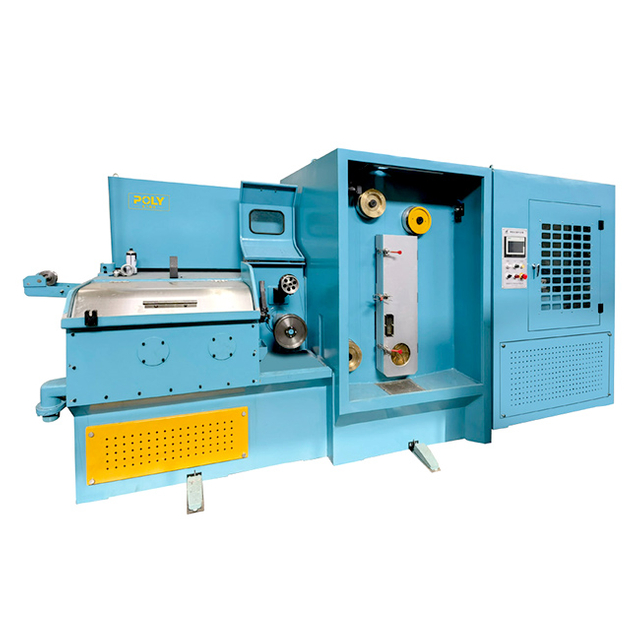
Drawing inherently work-hardens copper, making it brittle. Modern machines solve this using continuous inline annealing. This mechanism uses the copper wire itself as a resistance heating element. The system applies electrical current to push wire temperatures to 350°C–650°C. A thermal shock quench instantly follows this heating phase. Annealing synchronicity is completely non-negotiable. The heating voltage must perfectly match the real-time drawing speed. This synchronicity restores metal ductility and helps achieve 100% IACS conductivity.
Friction management ultimately determines your surface quality. Pulling metal through a tight die generates immense heat. A capable machine manages cooling emulsion flawlessly. Ideal fluid consumption benchmarks heavily around 0.1 to 0.25 liters per metric ton of copper processed. You must maintain a strict operating temperature window. The emulsion performs best between 35°C and 45°C. Operating outside this window breaks down the hydrodynamic lubrication layer.
Engineering realities often clash with production demands. You must monitor specific physics-based parameters to prevent catastrophic quality failures.
Many operators mistakenly believe faster speeds linearly increase friction. The Stribeck Curve proves this assumption false. Friction actually drops initially as drawing speed increases. The fluid creates a hydrodynamic wedge, separating the wire from the die. However, this hits a critical threshold. Often around 15 m/s, fluid shear stress builds rapidly. Fluid friction rebounds and heat spikes. Operating past your machine's designed speed limits fundamentally degrades surface quality.
Housekeeping realities dictate emulsion lifespan. Factory water quality directly impacts your lubrication. Hard water introduces calcium and magnesium. Salt-based softeners increase emulsion electrical conductivity. Both scenarios break down the chemical boundary of your drawing lubricant. When the boundary fails, metal touches metal. This leads to severe scoring on the wire surface. You must mix fluids using purified or reverse-osmosis water to protect your tooling.
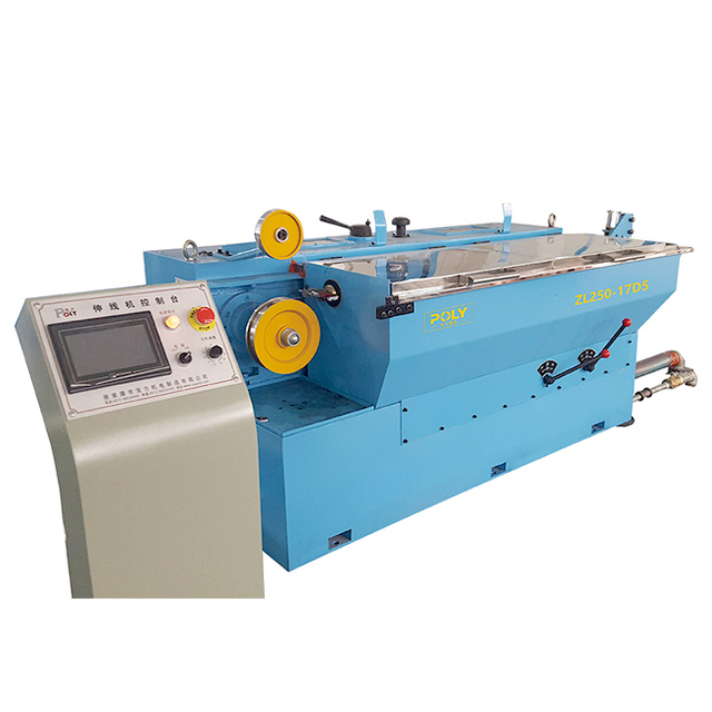
Wire must flow smoothly from payoff to spooling. Unsynchronized payoff creates severe tension imbalances. Sudden jerks stretch the copper, altering its delicate diameter. Conversely, low tension causes wire sagging and tangling. Both extremes lead to frequent wire breaks. robust PLC tension control loops solve this issue. They utilize dancer arms and digital feedback to maintain perfect tension across all speed variations.
Choosing the right equipment requires a structured approach. Follow this four-stage framework when shortlisting your next machinery investment.
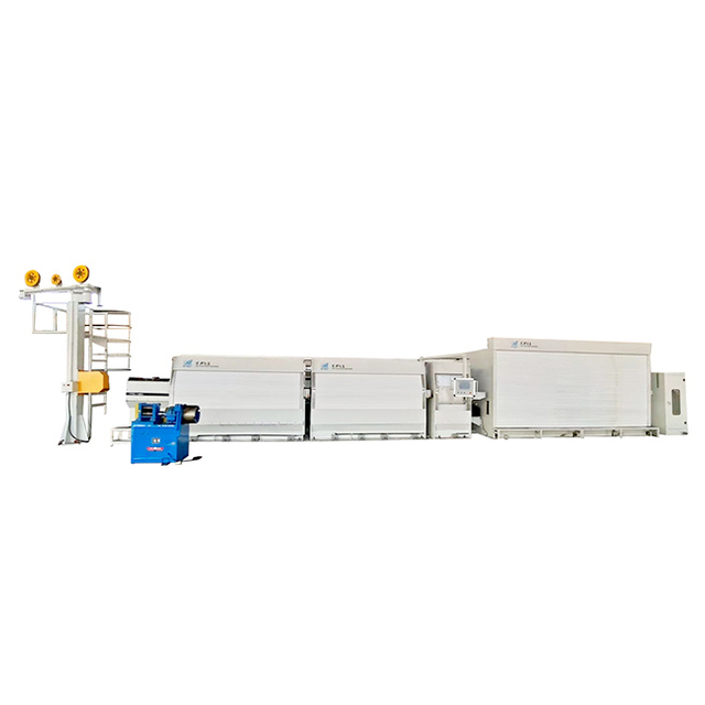
Stage 1: Define the Input/Output Matrix. You must match the machine type to your exact specifications. Determine if you need a Rod Breakdown machine for 8mm copper. Alternatively, specify if intermediate or fine draw machines suit your AWG/mm output requirements better.
Stage 2: Assess Process Automation (PLC & Drives). Require independent motor drives for critical capstans. Demand real-time digital tension feedback integration. These automation features prevent wire snapping during aggressive acceleration or deceleration phases.
Stage 3: Fluid & Cooling Architecture. Evaluate the integration of positive displacement mixing systems. Inspect the closed-loop cooling architecture. These systems ensure your expensive diamond tooling remains safely within the optimal hydrodynamic lubrication zone.
Stage 4: OEM Support & Commissioning. Gauge the supplier's engineering depth. They must assist with complex die sequencing. Ensure they offer initial process parameter optimization. A reliable copper wire drawing machine provider acts as a long-term technical partner, not just a vendor.
Measuring the quality of drawn copper wire goes far beyond a simple micrometer check. It requires a systemic, deeply rigorous evaluation of mechanical, electrical, and chemical properties. Minor deviations in any single pillar will sabotage your downstream manufacturing processes.
The quality of your final output acts as a direct reflection of your equipment's foundational engineering. Specifically, it highlights the precision of die alignment, the synchronicity of continuous annealing, and the robustness of fluid management. You cannot out-process a poorly engineered machine.
We strongly encourage buyers to demand hard evidence before committing capital. Request comprehensive sample run data from the manufacturer. Ask to review finite element method (FEM) die stress simulations. Engage in deep technical consultations with equipment builders to ensure their hardware matches your stringent production tolerances.
A: This is typically an issue with the continuous inline annealing process. If the temperature falls below the required 350°C–650°C window or the wire speed is unsynchronized, internal stress from work-hardening remains, reducing elongation.
A: Generally, once the total cross-sectional area reduction exceeds 50%, intermediate annealing is strictly required to restore the metal's crystalline structure and prevent fracture during subsequent draws.
A: Continuous monitoring is best. At a minimum, daily checks using a refractometer should be performed to ensure concentration levels are stable and operating temperatures remain safely between 35°C and 45°C.

 English
 简体中文
简体中文

