
- Home
- Products
- Company
- Solutions
- Advantages
- Blog
- Contact
- Hot
Views: 0 Author: Site Editor Publish Time: 2026-08-18 Origin: Site


Intermediate drawing sits at the critical center of wire manufacturing, acting as the bridge where high-volume reduction meets strict precision requirements. This stage directly impacts overall plant yield and downstream wire quality. Plant managers face a persistent operational challenge: bridging the gap between heavy rod breakdown and delicate fine wire processing without introducing bottlenecks, material fatigue, or excessive energy consumption. Achieving this requires precise equipment selection based on hard metallurgical facts and production line realities. You need a technical evaluation framework to choose the right machinery. This guide explores how to select an intermediate wire drawing machine based on material properties, inlet and outlet gauge requirements, and continuous annealing capabilities. We will also cover maximum drawing speeds and integration with your existing line architecture to ensure seamless production flow and eliminate unnecessary downtime.
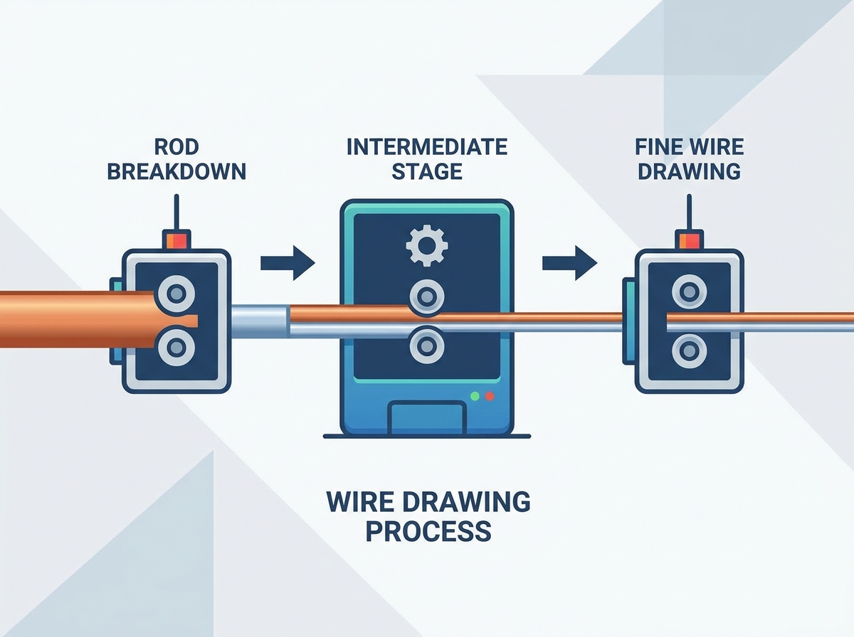
Strategic Positioning: Intermediate machines must seamlessly bridge the output of a rod breakdown machine and the input requirements of a fine wire drawing machine.
Material Specificity: While versatile, a combined copper and aluminum wire drawing machine requires distinct cooling, lubrication, and tension control profiles to prevent material failure.
Annealing Integration: Selecting a machine with integrated continuous annealing (especially for copper) reduces floor space and eliminates secondary processing steps.
Long-Term Viability: Long-term viability depends on capstan wear resistance, die life optimization, energy efficiency, and PLC-driven tension stability rather than upfront machine cost alone.
The intermediate drawing stage functions as the primary transition zone in a wire mill. It takes the coarse output from upstream processes and refines it for final sizing. Standard inlet wire sizes for this equipment typically range from 2.5mm to 3.5mm. However, production lines utilizing older or highly specialized configurations frequently feed heavier 5.5mm to 6.5mm stock directly from a rod breakdown machine. The intermediate equipment must handle these varying inlet diameters without stalling or causing excessive die wear. The gearboxes and drive motors must possess the torque necessary to initiate the draft on these heavier gauges without hesitation.
On the output side, target wire sizes generally range from 2.0mm down to 0.4mm. Achieving these specific dimensions is necessary to feed a downstream fine wire drawing machine, supply stranding lines, or prepare the wire for direct spooling. The intermediate machine must maintain strict dimensional tolerances across this entire reduction range. If the outlet wire is out of specification, it will immediately cause die jams or wire breaks in the subsequent fine drawing stages. Operators rely on this stage to correct any minor ovality issues inherited from the rod casting process.
Process Stage | Typical Inlet Diameter (mm) | Typical Outlet Diameter (mm) | Primary Downstream Application |
|---|---|---|---|
Standard Intermediate | 2.5 - 3.5 | 1.0 - 2.0 | Building wire, standard stranding |
Heavy Intermediate | 4.5 - 6.5 | 1.5 - 2.5 | Power cable cores, heavy automotive |
Fine-Prep Intermediate | 2.0 - 2.5 | 0.4 - 0.8 | Data cables, electronics, fine wire feed |
Evaluating intermediate processing requires establishing strict baseline performance metrics. Consistent diameter tolerance is the primary indicator of machine health. The equipment must hold tolerances within micrometers to ensure uniform electrical resistance in the final cable. Surface finish quality is equally important. Any scratching, scoring, or oxidation introduced at this stage will amplify during further reduction, leading to rejected batches. A flawless surface finish is non-negotiable for enameled wire applications or high-frequency data cables.
Uninterrupted continuous drawing speeds serve as the ultimate test of operational efficiency. Evaluating maximum meters-per-second (m/s) capabilities reveals the true throughput potential of the line. Modern intermediate lines often push speeds of 25 to 35 m/s depending on the final gauge. However, raw speed means nothing without synchronized speed control and mechanical stability. The machine must dynamically adjust tension across all capstans to prevent wire slippage. Slippage leads to capstan scoring, which degrades the wire surface and causes severe production bottlenecks. Precise synchronization ensures the wire remains taut but unstressed as it moves through the die sequence.
Copper and aluminum behave entirely differently under drawing tension. Copper possesses a high tensile strength. It requires significant pulling force to deform through the die sequence. The machinery handling copper must feature robust gearboxes, heavy-duty bearings, and high-torque motors to maintain steady reduction without stalling. The high friction generated during copper drawing also demands aggressive heat dissipation strategies, often requiring internal water cooling within the drawing blocks themselves.
Aluminum is much softer and highly susceptible to elongation. Applying the same tension profiles used for copper will cause aluminum wire to stretch, neck down, and snap instantly. Aluminum requires highly sensitive tension control, often utilizing advanced dancer arms and low-inertia capstans. You must assess the viability of utilizing a dual-purpose copper and aluminum wire drawing machine versus dedicating separate lines. While dual-purpose machines offer flexibility for smaller operations, dedicating separate lines eliminates the severe risk of cross-contaminating drawing lubricants, which can ruin surface finishes and accelerate die wear.
The chemical and thermal management of the drawing process dictates the lifespan of your tooling. Emulsion and lubricant types vary strictly by material. Aluminum processing relies heavily on high-viscosity synthetic drawing oils. These oils prevent the soft aluminum from galling and sticking to the capstans or dies. Copper processing requires water-based emulsions. These emulsions prioritize rapid cooling over heavy lubrication due to the intense heat generated by copper deformation.
You must evaluate the machine's internal fluid management system thoroughly. Look for high-capacity filtration units capable of removing microscopic metal fines from the lubricant pool. If fines recirculate, they act as an abrasive paste, destroying the wire surface and the dies. Heat exchanger efficiency is another critical factor. The cooling system must maintain optimal die temperatures continuously. Overheated dies expand, altering the wire diameter and causing immediate tolerance failures. Proper fluid management extends die life by thousands of kilometers of drawn wire.
Material | Lubricant Type | Primary Function | Filtration Requirement |
|---|---|---|---|
Copper | Water-based emulsion (4-8% concentration) | Rapid heat dissipation, moderate lubrication | Paper band or hydrocyclone filtration for fine copper dust |
Aluminum | Neat synthetic oil (High viscosity) | Heavy boundary lubrication, galling prevention | Earth filters or centrifuge systems for sticky aluminum fines |
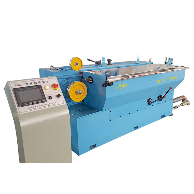
The physical layout of the capstans determines how the wire travels and deforms. You must choose between straight-line and cone-type capstan configurations. Straight-line machines offer torsion-free drawing. The wire travels in a direct path without twisting. This torsion-free output is critical for specific downstream applications like mesh welding or the production of specialty high-frequency cables. Cone-type machines are more compact but introduce slight bending and twisting forces, which are generally acceptable for standard electrical building wire.
Capstan surface treatments directly impact maintenance schedules. Standard steel capstans wear quickly under high-speed production. Evaluate machines featuring tungsten carbide coatings or solid ceramic rings. These materials offer exceptional wear resistance and longevity, preventing the formation of grooves that cause wire slippage. Furthermore, assess the drive configuration. Compare individual AC motor drives against single-motor group drives. Dual-inverter systems with individual drives provide precise slip control, allowing the machine to adjust instantly to minor variations in wire elongation. This active slip compensation prevents wire breaks during acceleration and deceleration phases.
Proper reduction planning prevents wire hardening and breakage. You must calculate the optimal area reduction per draft based on the material. Typically, reductions range from 15% to 25% per die. Pushing beyond this limit work-hardens the metal too rapidly, making it brittle and prone to snapping. The machine must accommodate the correct number of dies to achieve the total required reduction smoothly. The geometry of the dies themselves, specifically the approach angle and bearing length, must match the material being drawn.
Evaluate the machine's die holder design. Alignment precision is non-negotiable. If a die sits even slightly off-center, it will shave the wire unevenly, creating oval-shaped output and generating excessive metal dust. Additionally, examine the ease of rapid tooling changeovers. Operators need quick-release mechanisms and accessible die boxes to minimize downtime when switching between different wire gauges. Pressure die holders, which force lubricant into the die approach angle, are highly recommended for extending die life during high-speed runs.
Drawing inherently hardens metal. For copper wire in the 0.4mm to 1.6mm range, in-line annealing is a technical necessity. It restores ductility immediately before spooling, allowing the wire to bend without fracturing during later stranding or installation. Integrating this process directly into the drawing line saves massive amounts of floor space and eliminates the need for slow, batch-style bell furnaces. The annealer must track the line speed perfectly to apply the correct voltage, ensuring uniform softness throughout the entire spool.
When evaluating annealing systems, compare DC versus AC technologies. DC annealers generally provide smoother surface finishes for fine wires, while AC systems are robust and easier to maintain. Inspect the contact ring durability, as these components endure constant friction and electrical arcing. Nickel-alloy contact bands often provide the best balance of conductivity and wear resistance. Finally, verify the integration of steam or nitrogen protection zones. These inert atmospheres surround the hot wire as it exits the annealer, preventing rapid oxidation and keeping the copper bright and conductive. A dedicated drying phase immediately following the cooling bath is also required to prevent water stains on the finished wire.
Production volume dictates the choice between multi-wire and single-wire architectures. Multi-wire drawing machines pull 4, 8, or even 16 wires simultaneously through parallel die sets. This provides an exponential increase in high-volume output, making it ideal for massive runs of standard building wire or automotive cables. However, this throughput comes with significant operational complexity. The initial setup requires meticulous attention to detail to ensure all wires are tensioned equally.
Single-wire machines offer operational simplicity and maximum flexibility. They are perfect for facilities that frequently change wire sizes or run specialized alloys. Evaluate the impact of multi-wire setups on your die maintenance schedules. A 16-wire machine requires managing hundreds of dies simultaneously. String-up times also increase dramatically. If one wire breaks in a multi-wire setup, the entire machine must stop, reducing the overall equipment effectiveness (OEE) if operators are not highly skilled in rapid recovery procedures.
Facility layout and utility capacities play a major role in equipment selection. Multi-wire machines offer a highly condensed footprint per wire produced. You can generate four times the output in roughly the same physical space as a single-wire machine. However, the concentrated power draw requires heavy-duty electrical infrastructure and massive coolant reservoirs to handle the simultaneous heat generation from multiple drawing paths.
Analyze the kilowatt-per-kilogram energy consumption metrics between the two architectures. Multi-wire machines often operate more efficiently at full capacity, spreading the baseline mechanical losses across multiple wires. Single-wire machines might consume slightly more energy per kilogram of output but offer the ability to power down entirely during low-demand periods without halting the entire plant's production flow. This modularity allows plant managers to scale production up or down based on immediate order requirements without wasting baseline energy.
Wire breakage destroys production schedules and wastes raw material. Identifying the primary causes of intermediate wire breakage is the first step in mitigation. Die wear is the most common culprit, altering the reduction ratio and spiking the pulling tension. Improper lubricant concentration leads to friction buildup, causing the wire to snap from thermal stress. Tension spikes caused by mechanical binding or electrical faults also result in immediate breaks. Operators must monitor the drawing fluid concentration daily using refractometers to prevent lubrication failures.
Evaluate machine features designed to mitigate these risks actively. Automated tension dancers absorb sudden mechanical shocks and feed real-time position data back to the drives. Precise PLC synchronization ensures all capstans accelerate and decelerate in perfect harmony, maintaining steady tension. Quick-stop braking systems are essential. If a break occurs, the machine must halt instantly to prevent the loose wire from tangling around the capstans and causing hours of downtime. Pneumatic disc brakes on the main drive shafts provide the rapid deceleration required for this safety feature.
The intermediate drawing machine does not operate in isolation. It must hand off the finished wire to the next stage flawlessly. Assess the compatibility of the drawing machine with automatic dual-spoolers, dynamic coilers, and direct-feed systems utilized for bunching or stranding lines. The communication between the drawing line and the spooler must be instantaneous. The spooler's traverse mechanism must lay the wire perfectly flat across the bobbin to prevent tangles during subsequent payoff operations.
Evaluate the traverse mechanisms and tension control during the spool changeover process. Automatic dual-spoolers must cut and transfer the flying wire to an empty bobbin at full production speed. This requires zero-slip tension control to ensure zero production loss. A seamless transition here prevents the wire from loosening or overlapping improperly, which would cause tangles when feeding the subsequent fine wire drawing machines. The pintle design on the spooler should also allow for rapid, tool-less bobbin loading and unloading to keep operator intervention to an absolute minimum.
Industrial drawing equipment operates under extreme continuous stress. You must outline the expected lifecycle of high-wear components before installation. Capstans, electrical contact bands in the annealer, and high-speed spindle bearings will require regular replacement. Understanding these intervals allows for accurate maintenance scheduling and prevents catastrophic mid-run failures. Implementing vibration analysis on the main drive bearings can predict failures weeks before they cause a line stoppage.
Evaluate the vendor's supply chain transparency. You cannot afford to wait weeks for proprietary parts to ship internationally. Prioritize machines built with standardized electrical components from globally recognized brands. Standardized PLCs, inverters, and motors ensure that your local maintenance team can source replacements quickly and troubleshoot faults without relying entirely on the original manufacturer. Mechanical components like seals, belts, and pulleys should also conform to standard metric or imperial sizes available from local industrial suppliers.
Modern wire production relies heavily on data. Assess the value of integrated HMI and PLC systems. These interfaces should offer real-time fault diagnostics, pinpointing exactly which sensor or drive triggered a stoppage. This eliminates the guesswork for operators and drastically reduces mean time to repair (MTTR). The HMI should display real-time line speed, annealing voltage, and dancer positions on a single, easy-to-read dashboard.
Look for robust recipe management capabilities. The system should store tension profiles, annealing voltages, and speed settings for different wire gauges and materials. This allows operators to switch production runs with a single button press, ensuring consistency across shifts. Furthermore, verify the system's ability to integrate with plant-wide ERP or MES systems. Capturing real-time data on wire breaks, energy consumption, and total output length provides the visibility needed to optimize the entire factory floor and accurately calculate production yields.
Request empirical test runs using your facility's specific copper or aluminum rod stock to verify the machine's tension control and surface finish capabilities.
Conduct a comprehensive die-sequence audit with the manufacturer to ensure the reduction ratios match your exact material specifications.
Verify the vendor's post-installation support infrastructure, focusing on local spare parts availability for critical components like capstans and contact rings.
Standardize your lubrication protocols based on the material types to prevent cross-contamination and extend tooling life.
A: Intermediate machines typically accept inlet wire ranging from 2.5mm to 6.5mm directly from rod breakdown stages. They reduce this material down to an outlet size of 0.4mm to 2.0mm. This specific reduction range perfectly bridges the gap between heavy rod processing and delicate fine wire drawing.
A: While technically possible with a combined machine, it requires rigorous cleaning of the entire lubrication system between runs. Copper uses water-based emulsions, while aluminum requires synthetic oils. You also need different die geometries and tension profiles to prevent cross-contamination and frequent wire breakage.
A: The mechanical drawing process severely hardens the metal. In-line continuous annealing applies controlled electrical current to heat the wire, restoring its ductility immediately before spooling. This integrated step saves massive amounts of floor space and entirely eliminates the need for slow, batch-style annealing furnaces.
A: A rod breakdown machine utilizes massive capstans and extreme pulling force to crush heavy 8mm cast rod. Intermediate machines operate at much higher speeds with smaller die sequences. They focus on precision tension control and exact dimensional tolerances rather than raw, heavy-duty material reduction.
A: Multi-wire machines pull 4, 8, or 16 wires simultaneously. This provides an exponential increase in production throughput and significantly reduces the factory footprint required per wire. However, they introduce higher operational complexity regarding initial string-up procedures and simultaneous die maintenance.
A: Slip machines allow the wire to slide slightly on the capstan surface to naturally match speed differentials between drafts. Non-slip, or straight-line machines, use individual drives to achieve zero-slip. This prevents wire torsion and twisting, making non-slip machines preferable for specific alloys or profiled wires.
A: The primary culprits include incorrect die reduction ratios that over-stress the metal, degraded or contaminated drawing emulsion, and heavily worn capstans. Tension mismatches between the drawing section and the continuous annealing section will also cause the wire to snap instantly during high-speed runs.


 English
 简体中文
简体中文
