
- Home
- Products
- Company
- Solutions
- Advantages
- Blog
- Contact
- Hot
Views: 0 Author: Site Editor Publish Time: 2026-09-01 Origin: Site


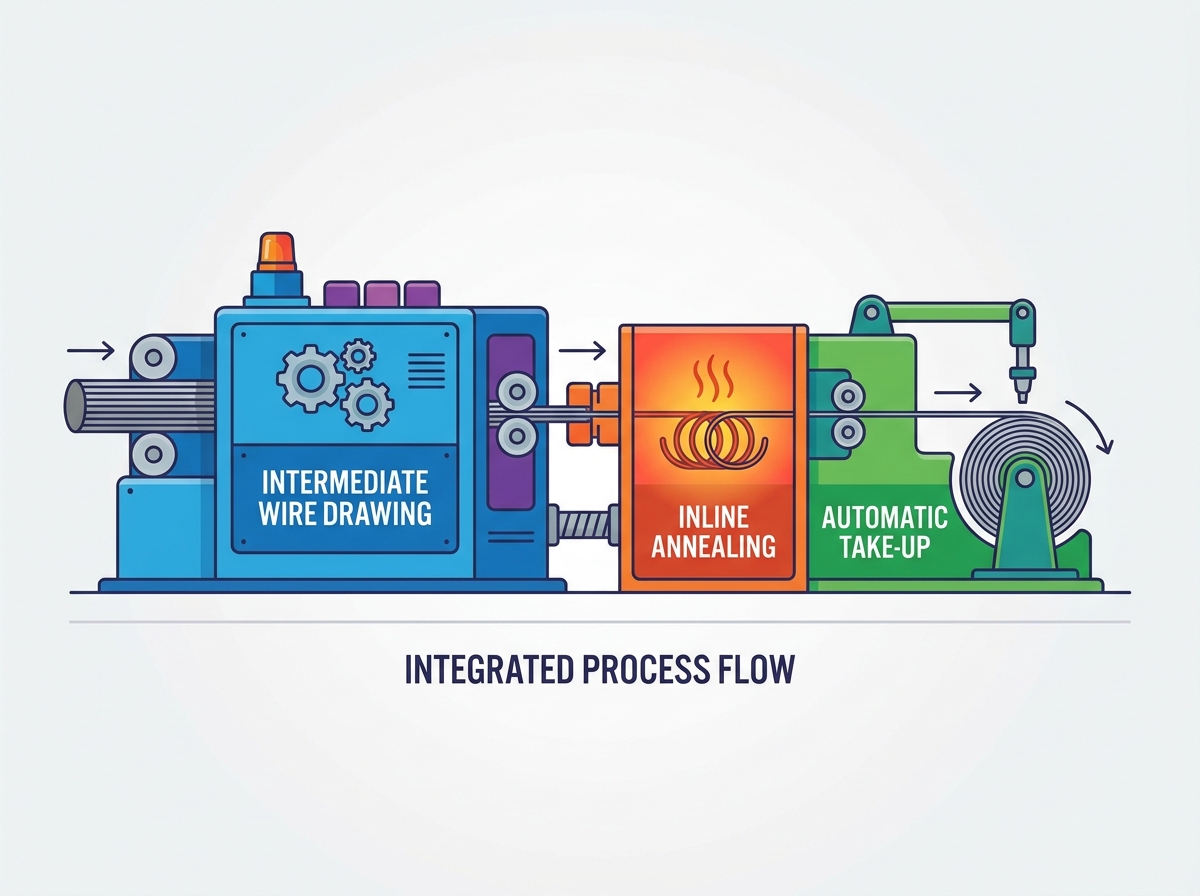
Operating disconnected wire drawing, annealing, and spooling processes introduces severe bottlenecks. You face inconsistent wire elongation, high scrap rates, and excessive manual handling when these stages run independently. Achieving continuous, high-speed production requires precise synchronization between mechanical drawing speeds, thermal annealing parameters, and spooling tension. A failure to integrate these stages results in wire breakage, surface defects, and costly downtime on the factory floor. The physical transition of metal from a hardened, drawn state to a softened, annealed state demands uninterrupted tension control. Successfully deploying an integrated line requires evaluating specific drive architectures, closed-loop control systems, and continuous spooling technologies. This guide breaks down the technical requirements for integrating drawing, annealing, and take-up equipment into a unified, high-yield production system. We cover mechanical alignment, electrical synchronization, and control logic implementation to ensure your production line operates at maximum efficiency.
Synchronization is Critical: Seamless integration relies on PLC-driven closed-loop feedback to match the RPM of the drawing capstans with the annealing voltage and take-up speed.
Thermal Consistency Dictates Quality: Utilizing a 3-stage independent DC annealing system prevents oxidation and ensures uniform elongation properties across the entire wire length.
Continuous Operation Drives ROI: Pairing the drawing line with an automatic take-up machine featuring dual-spool, non-stop changeover capabilities eliminates deceleration downtime.
Specification Alignment: Selecting the correct intermediate wire drawing machine specifications—specifically dual-inverter AC drives and optimized capstan layouts—is the baseline for successful downstream integration.
Integration begins with establishing strict operational baselines for the entire production line. You must define the target input and output diameters. A typical intermediate line takes 2.5mm to 3.5mm copper rod and draws it down to finished diameters ranging from 0.4mm to 1.2mm. You also need to establish the maximum allowable line speed, often pushing 25 to 35 meters per second, alongside the required tensile strength and elongation percentages. Annealed copper generally targets a tensile strength of 200 to 250 N/mm². These metrics dictate the mechanical and electrical limits of the integrated system. If the drawing unit pushes wire faster than the annealer can uniformly heat it, the final product fails quality control tests. Establishing these baselines ensures you size the motors, drives, and heating elements correctly to handle continuous loads without overheating or tripping fault sensors.
Different metals behave uniquely under mechanical stress and thermal treatment. Copper wire requires specific horizontal contact-type annealing profiles to achieve maximum electrical conductivity, typically reaching annealing temperatures between 400°C and 500°C. The integration must account for rapid heat transfer and immediate water quenching to prevent oxidation. Aluminum and specialized alloys demand distinct tension limits and thermal curves. Aluminum is highly susceptible to necking and breakage under high tension at elevated temperatures. Processing these materials requires highly sensitive dancer rolls and lower tension setpoints between the final drawing die and the annealing contact rings to maintain structural integrity.
The transition zone between the final drawing capstan and the annealer entry represents the highest risk area for wire breaks. As the wire exits the drawing section, it remains work-hardened and under significant mechanical tension. Entering the annealer, the wire heats up and softens, fundamentally changing its tensile properties. Overcoming this mismatch requires precise dancer roll calibration. The dancer roll provides physical buffering, absorbing minor speed variations while sending continuous analog signals to the drive controllers. A typical dancer in this zone requires 0.5 to 1.5 bar of pneumatic pressure depending on the wire gauge. Proper calibration ensures the wire remains taut enough to maintain electrical contact on the annealing rings but loose enough to prevent stretching as the metal softens.
The ultimate measure of integration success is the Overall Equipment Effectiveness (OEE) of the combined line. A successful deployment minimizes wire breaks during the acceleration and deceleration phases. Start-up sequences are inherently unstable; matching the acceleration ramp of the drawing motors with the voltage ramp of the annealer prevents snapping. High OEE also depends on maximizing the uptime percentage between spool changes. A standard 5-minute spool changeover downtime every hour reduces OEE by over 8%. By eliminating the need to stop the line to swap full spools for empty ones, the system maintains thermal equilibrium, reduces scrap, and increases total daily output.
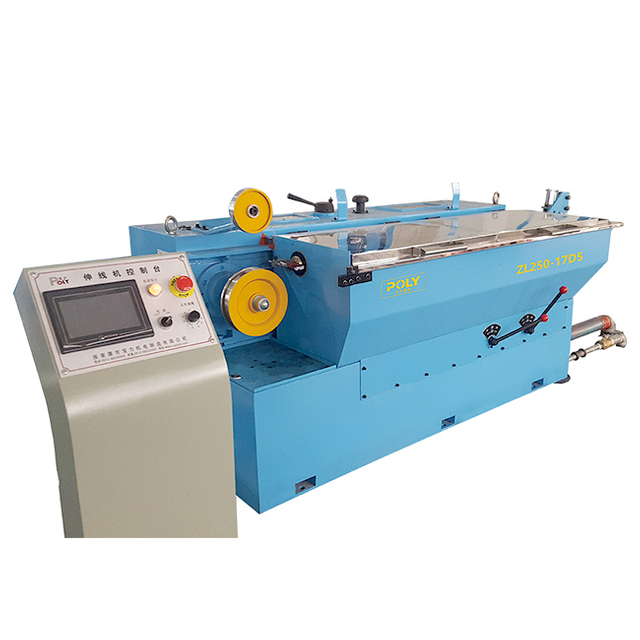
Drive architecture forms the foundation of a synchronized line. Evaluating intermediate wire drawing machine specifications requires a close look at the motor configurations. You need AC three-phase dual-inverter drives for independent control of the main drawing capstans and the final exit capstan. A dual-inverter setup allows the system to electronically manage the slip ratio at the final die, typically keeping it between 0% and 2%. This independent control reduces surface abrasion on the wire and minimizes wear on the capstan surfaces. Single-motor systems rely entirely on mechanical drafting ratios, offering no flexibility to adjust tension dynamically before the wire enters the annealer.
Feature | Single-Motor Drive Architecture | Dual-Inverter AC Drive Architecture |
|---|---|---|
Capstan Control | Mechanically linked, fixed slip ratio. | Independent control of final capstan. |
Tension Adjustment | Manual die changes required to adjust tension. | Electronic adjustment via PLC feedback. |
Wire Surface Quality | Higher risk of scratching due to mechanical slip. | Minimized abrasion; smoother surface finish. |
Integration Readiness | Poor; difficult to sync with inline annealers. | Excellent; native support for closed-loop control. |
Capstan material and lubrication directly impact the thermal state of the wire before it reaches the annealing stage. Tungsten carbide coatings on the drawing capstans provide the hardness required to withstand continuous friction while maintaining a smooth surface. Some manufacturers use ceramic-coated capstans for better wear resistance, though they offer poorer heat dissipation. Friction generates intense heat, making high-flow lubrication systems mandatory. The drawing emulsion must flood the dies and capstans at flow rates exceeding 150 liters per minute to keep the wire cool. If the wire enters the annealer already overheated from poor lubrication, the pre-set annealing voltages will over-bake the metal, leading to structural failure.
Reviewing OEM specifications regarding the area reduction per draft is a strict engineering requirement. The machine must handle the specific alloy without exceeding motor torque limits. A typical intermediate machine uses 13 to 17 dies. The area reduction usually starts around 26% at the inlet and drops to roughly 15% at the final finishing die. Each die reduces the cross-sectional area of the wire, requiring a specific amount of pulling force. If the drafting ratio is too aggressive for the selected motor size, the drives draw excessive current, leading to thermal faults. You must calculate the total area reduction from the inlet rod to the finished wire and verify that the mechanical limits align with your production targets.
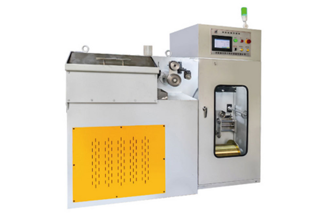
The physical layout of the drawing unit impacts installation and long-term maintenance. You must determine whether a modular design or a monoblock chassis best suits your facility. In a modular design, the drawing section is physically independent but electronically linked to the annealer and take-up. This allows for easier maintenance access and the flexibility to upgrade individual components later. A monoblock footprint integrates the drawing and annealing sections onto a single heavy-duty frame. While this saves floor space and simplifies alignment during installation, it restricts access to internal components during routine servicing.
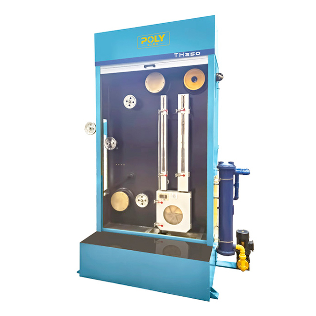
Choosing the right annealing technology determines the consistency of the wire's physical properties. Deploying an intermediate wire drawing machine with annealer involves comparing horizontal contact-type DC annealing against AC alternatives. For intermediate wire sizes, 3-stage DC independent annealing provides superior control. Stage one pre-heats the wire to roughly 200°C. Stage two pushes the temperature to the full annealing point around 500°C. Stage three reheats the wire slightly after the quench to ensure it dries completely. DC current flows evenly through the cross-section of the wire, preventing the skin effect associated with AC systems. This uniform heat distribution yields consistent elongation properties for downstream applications like stranding or enameling.
The core challenge of inline annealing is dynamic electrical synchronization. The control logic must automatically scale the annealing voltage and current in direct proportion to the drawing machine's RPM. During acceleration, the wire spends more time between the contact rings; if the voltage remains static, the wire melts. As RPM levels rise, the electrical output must shift instantaneously to ensure consistent joule heating. This requires high-speed communication between the drive encoders and the annealing thyristors. A well-calibrated PID loop controls the thyristor firing angle, ensuring the energy delivered to the wire remains constant per meter regardless of line speed.
Heating the wire is only half the process; cooling it without causing oxidation requires strict environmental control. As the wire reaches its peak annealing temperature, it becomes highly reactive to oxygen. The integration must include a sealed cooling zone where the wire is immediately quenched in water. The coolant system needs a dedicated heat exchanger to maintain water temperatures between 35°C and 40°C. To prevent oxidation before the quench, the heating zone must be flooded with steam or nitrogen, displacing ambient oxygen. Following the quench, high-velocity air wipes operating at 5 bar of compressed air must strip all residual moisture from the wire. Water carried over into the take-up spool causes severe corrosion.
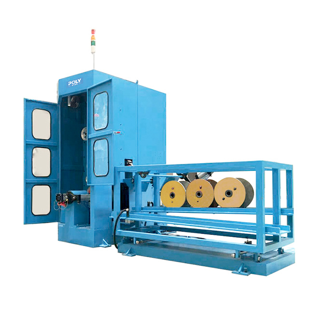
To capitalize on the high speeds of the drawing and annealing stages, the spooling process must not interrupt production. Routing the finished wire into an automatic take-up machine equipped with dual spools enables non-stop operation. The mechanical requirements include an automated snagger and a flying cut-off mechanism. When the primary spool reaches its target length, the machine accelerates the empty secondary spool to match the exact line speed. The traverse unit rapidly shifts the wire to the empty spool, where the snagger catches it. The flying knife cuts the transition wire in milliseconds, all without slowing down the upstream equipment.
The quality of the wound spool directly affects the efficiency of subsequent manufacturing steps. Servo-driven traverse units maintain a flat, even lay on the spool. The traverse speed must be electronically geared to the rotational speed of the spool and the diameter of the wire. Operators adjust the pitch settings based on the specific wire gauge. If the traverse moves too slowly, the wire piles up at the flanges; if it moves too quickly, gaps form, causing the wire to tangle during payoff. Precision spooling is mandatory for applications like magnet wire enameling or high-speed data cable extrusion.
Maintaining constant winding tension prevents wire stretching or loose wraps. The take-up machine's PLC communicates continuously with the annealer's exit dancer. As the spool fills, its diameter increases, meaning the rotational speed must decrease to maintain a constant linear wire speed. The tension regulation system uses feedback from the dancer to adjust the torque of the take-up motor dynamically. Advanced systems utilize a taper tension winding profile. As the spool fills, the tension decreases slightly to prevent the outer layers from crushing the inner layers, preserving the elongation properties achieved in the annealing stage.
Operating a synchronized line requires a centralized control panel that consolidates data from all three machine sections. A unified HMI provides operators with real-time visibility into drawing speed, annealing current, take-up tension, and fault diagnostics. Operators navigate through specific screens such as Drive Status, Annealing Curve, Fault History, and Maintenance Timers. Instead of monitoring separate panels, the operator views the entire process flow on a single interface. If a tension fault occurs at the take-up, the HMI displays the exact sensor triggering the alarm, reducing troubleshooting time and minimizing production losses.
The physical integration of the machines relies entirely on the digital integration of their sensors. Encoders on the drawing capstans track the exact mechanical speed. Voltage and current sensors in the annealer monitor the thermal energy delivery. Tension sensors and dancer potentiometers in the take-up loop measure the physical strain on the wire. All these devices communicate via a high-speed industrial ethernet protocol, such as PROFINET or EtherCAT, which boast scan times of 1 to 2 milliseconds. This network allows the main PLC to process thousands of data points per second, making micro-adjustments to the drives to maintain perfect system equilibrium.
Switching production between different wire diameters or materials consumes time and introduces human error. Programmable logic controllers capable of storing specific parameter recipes eliminate operator guesswork. A recipe includes the exact drawing speed, annealing voltage curve, quench water flow rate, and take-up tension required for a specific product. When a changeover is required, the operator selects the recipe from the HMI, and the PLC automatically configures all machine settings. This standardized approach reduces setup time, ensures batch-to-batch consistency, and lowers the reliance on highly experienced operators for routine adjustments.
The highest risk of wire breakage occurs during the initial acceleration phase. When the line starts from a standstill, the static friction in the drawing dies and the inertia of the take-up spools create massive tension spikes. To mitigate this, the control system utilizes programmed S-curve acceleration profiles and soft-start inverter settings. The PLC commands the drawing motors to accelerate gradually, allowing the dancer rolls time to adjust and buffer the tension. Simultaneously, the annealing voltage follows a synchronized ramp curve to prevent the slow-moving wire from overheating and snapping before reaching full production speed.
Inline annealers operate in high-maintenance environments due to the combination of electricity, water, and continuous friction. The contact rings, carbon brushes, and nickel bands wear down over time. If a contact ring becomes grooved or pitted, it causes electrical arcing, which instantly damages the wire surface and creates weak spots. Implementing predictive maintenance schedules prevents this damage. Operators must inspect and replace carbon brushes roughly every 1000 operating hours and dress the contact rings at specified intervals. Monitoring the electrical draw indicates wear; a sudden increase in resistance points to degrading contact surfaces.
The drawing process uses a specialized emulsion to lubricate the dies, while the annealing process uses clean water to quench the heated wire. Cross-contamination between these two fluids severely degrades wire quality. If drawing emulsion enters the annealing quench zone, it burns onto the wire, destroying its electrical conductivity and surface finish. If annealing coolant dilutes the drawing emulsion, die wear accelerates rapidly. You must implement strict physical separation protocols, utilizing labyrinth seals, heavy-duty air wipes, and dedicated filtration systems to keep the fluid loops entirely isolated.
Mechanical Alignment: Anchor the drawing chassis and annealer frame to the foundation, ensuring a maximum deviation of 0.5mm across the wire path.
Fluid System Isolation: Pipe the drawing emulsion and annealing quench water through separate, color-coded manifolds to prevent accidental cross-contamination.
Electrical Terminations: Route high-voltage annealing cables away from low-voltage encoder signal wires to eliminate electromagnetic interference.
Sensor Calibration: Zero out the dancer roll potentiometers and verify the tension load cells against known physical weights.
Dry Run Testing: Execute a low-speed jog sequence without wire to confirm motor rotation direction and traverse unit limits.
When procuring equipment, you must decide between sourcing a turnkey solution from a single manufacturer or integrating components from multiple vendors. Purchasing a fully integrated intermediate wire drawing machine line from a single OEM guarantees native PLC compatibility. The drives, sensors, and HMI communicate out of the box, eliminating the need for custom programming and expensive system integrators. Piecemeal sourcing allows you to select highly specialized individual units, but the burden of electrical synchronization and software integration falls entirely on your engineering team, significantly increasing deployment risks.
The final application of the wire dictates the strictness of the manufacturing tolerances. Ensure the OEM has a proven track record in your specific sector. Automotive wire requires highly consistent elongation to withstand constant vibration. Building wire demands perfect surface finishes for smooth conduit pulling. Aerospace cables require specialized alloys that many standard drawing machines cannot process without exceeding torque limits. Request case studies and reference installations from the OEM that match your exact material and diameter specifications to verify their equipment meets your industry's compliance standards.
Integrating an intermediate wire drawing machine with inline annealing and automated take-up is a complex electrical and control-system synchronization that dictates final product viability. The physical alignment of the machinery is secondary to the digital communication between the drives, heating elements, and tension sensors. Without a closed-loop PLC architecture managing these variables in real-time, the line suffers from continuous wire breaks and inconsistent metallurgical properties.
When evaluating OEMs, prioritize vendors who supply the entire integrated line with a unified PLC architecture. The supplier must demonstrate dynamic voltage tracking across the full spectrum of line speeds, proving that the annealer adjusts instantaneously to mechanical fluctuations. Avoid manufacturers who treat the drawing, annealing, and spooling stages as isolated units bolted together after the fact.
Request comprehensive Factory Acceptance Testing (FAT) from the supplier before shipment to validate system integration.
Demand physical proof of continuous operation during dual-spool changeovers at maximum line speed.
Require metallurgical lab reports verifying wire elongation consistency across varying acceleration and deceleration phases.
Audit the OEM's HMI software to ensure recipe management and fault diagnostics are accessible and logically structured.
A: Focus on the maximum line speed, the type of drive system (dual-inverter AC is preferred), capstan diameter, and the maximum motor torque. These specifications dictate the mechanical boundaries and establish the synchronization limits required to match the inline annealer's thermal capacity.
A: The system uses a PLC and closed-loop feedback to monitor the RPM of the drawing capstans. It automatically adjusts the annealing voltage and current in real-time, ensuring the wire receives consistent joule heating regardless of acceleration, deceleration, or line speed fluctuations.
A: A 3-stage DC system provides precise, segmented control over the pre-heating, annealing, and drying phases. This independent control minimizes electrical arcing, prevents the skin effect, and yields highly uniform elongation properties essential for intermediate wire sizes.
A: It utilizes a dual-spool design equipped with an automated snagger and flying cut-off mechanism. When one spool is full, the machine automatically transfers the running wire to the empty spool at full production speed, eliminating the need to decelerate the drawing line.
A: Tension mismatches typically cause breakage. As the work-hardened wire enters the annealer and softens, its tensile strength drops. If the dancer rolls are improperly calibrated or the drive speeds desynchronize, the excess tension snaps the softened wire.
A: Flooding the high-temperature annealing zone with a protective atmosphere, such as steam or nitrogen, displaces oxygen and prevents oxidation. Immediately following the heating phase, the system rapidly quenches the wire in a sealed water cooling zone before exposure to ambient air.


 English
 简体中文
简体中文
