
- Home
- Products
- Company
- Solutions
- Advantages
- Blog
- Contact
- Hot
Views: 0 Author: Site Editor Publish Time: 2026-08-25 Origin: Site


Misaligning wire drawing stages leads to excessive die wear, frequent breakages, and compromised surface finish. Forcing primary equipment to handle medium reductions destroys operational efficiency. Feeding out-of-spec wire into fine drawing stages causes cascading filament failures. Plant managers and process engineers frequently struggle to define the exact transition point between primary reduction and final sizing. Industry terminology often overlaps, creating ambiguity. You risk capital expenditure on over-specced machinery. You also inflate operating expenses through inefficient, multi-pass setups that bottleneck production. This guide breaks down the technical thresholds, operational trade-offs, and integration requirements for medium and fine wire drawing equipment. We provide a practical framework to specify the correct machinery for your specific production line.
Define the Operational Bridge: An intermediate wire drawing machine (frequently referred to as a medium wire drawing machine) acts as the critical link between high-torque rod breakdown and high-speed final sizing, applying smaller reductions across more stages for precise surface control.
Inline Processing Drives Efficiency: Specifying an intermediate wire drawing machine with annealer eliminates batch processing bottlenecks, restores material ductility instantly, and reduces work-in-progress (WIP) inventory.
Volume vs. Precision: Fine wire drawing machines are engineered for multi-wire, high-speed processing of micro-diameters (typically 0.05mm to 1mm), requiring strictly controlled input from the intermediate stage to prevent filament breakage.
Primary reduction requires immense mechanical force. Manufacturers engineer the rod breakdown machine for maximum torque. It reduces large-diameter stock down to manageable intermediate gauges. You typically feed 8mm copper or 9.5mm aluminum rod into this equipment. The machine pulls this raw casting rod through a series of large tungsten carbide dies. The primary goal is bulk area reduction rather than surface perfection.
The payoff system for rod breakdown requires massive structural support. You must manage 5-ton coils of continuous cast rod. Snarl switches and tangle detectors sit at the entry point. If the rod catches on itself, the machine must execute an emergency stop within milliseconds. Failure to stop will rip the payoff stand from the floor. The entry guide rollers straighten the rod before it hits the first drawing die. This prevents uneven wear on the tungsten carbide.
Some legacy manufacturers refer to rod breakdown as the first intermediate draw. Modern production strictly categorizes this as primary reduction. The mechanical requirements differ vastly from downstream processes. Heavy AC motors drive massive capstans. The equipment operates with aggressive draft angles. It utilizes high reduction ratios per draft, often exceeding 25% area reduction per die. This aggressive processing results in lower surface finish control. You cannot use this output directly for final sizing operations.
The heavy drawing process generates extreme heat. Rod breakdown systems require thick, high-viscosity drawing oils or heavy emulsions. These lubricants prevent the rod from welding to the die under extreme pressure. The output wire typically ranges from 2.0mm to 3.5mm. This wire contains surface imperfections. It also suffers from severe work hardening. It requires further refinement before micro-sizing.
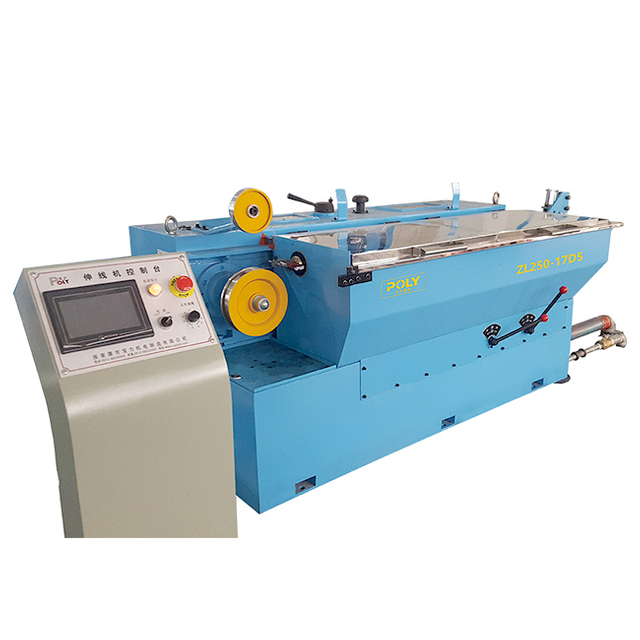
This equipment accepts the output from the primary stage. It acts as the operational bridge in your facility. An intermediate wire drawing machine applies sequential, smaller reductions across multiple capstans. Operators often categorize it as a medium wire drawing machine. It processes medium-sized copper, aluminum, and alloy conductors.
The intermediate stage delivers finer control over tensile strength. The process corrects surface imperfections left over from the aggressive breakdown stage. It refines the wire geometry. It prepares the material for final micro-reduction. The input wire enters at roughly 2.5mm to 3.5mm. It exits between 0.4mm and 1.2mm. This stage transitions from heavy tungsten carbide dies to polycrystalline diamond (PCD) dies.
Operators must monitor the slip rate across the intermediate capstans. Slip occurs when the capstan rotates faster than the wire travels. A controlled amount of slip is necessary to maintain tension. Too much slip generates excessive friction and heat. This burns the drawing emulsion and scores the wire surface. You adjust the draft schedule to optimize the slip rate. Proper die sequencing ensures the wire elongates at a rate matching the mechanical gearing of the capstans.
You must manage momentum and tension carefully here. The wire mass remains significant. Acceleration and deceleration phases require precise dancer control. The intermediate machine refines the grain structure of the metal. It utilizes moderate draft angles. The cooling systems transition from heavy oil to lighter, water-based emulsions. This ensures a clean, smooth surface finish.
This stage processes thin wires at extreme speeds. A fine wire drawing machine handles diameters dropping below 1mm down to 0.05mm. The equipment utilizes multi-wire configurations. You can draw 8, 16, or 32 wires simultaneously. The production speeds often exceed 30 meters per second.
Vibration isolation becomes essential at these extreme speeds. The machine frame must absorb high-frequency harmonics generated by the drive motors. Any vibration transferred to the die holders will cause micro-chatter on the wire surface. This chatter weakens the filament. We mount fine drawing machines on specialized dampening pads. The foundation must be completely isolated from heavy equipment like rod breakdown machines or stranding lines.
You need flawless input material to maintain high uptime. Cascading breaks will halt the entire line. If one wire snaps, it often tangles adjacent wires. This causes massive downtime. The fine stage relies on natural or synthetic single-crystal diamond dies. These dies provide the ultimate surface finish. They maintain strict dimensional tolerances.
Tension control becomes the primary engineering challenge. The micro-filaments possess very low tensile strength. Even minor tension spikes will snap the wire. The equipment uses ultra-sensitive electronic load cells. Micro-dancers provide real-time feedback to the drive motors. The spooling mechanism requires flawless traversing. Tangles at this stage will ruin downstream extrusion or stranding operations.
The intermediate stage utilizes a moderate draft per die. You focus on maintaining the structural integrity of the metal. The area reduction per die typically ranges from 15% to 22%. You want to achieve a smooth, uniform surface without over-stressing the material. The die geometry features a standard approach angle. The bearing length stabilizes the wire diameter.
Polycrystalline diamond (PCD) dies dominate the intermediate stage. PCD offers exceptional wear resistance compared to tungsten carbide. It withstands the moderate heat and friction of medium reductions. However, PCD lacks the absolute smooth surface of natural diamond. For final sizing below 0.1mm, natural single-crystal diamond remains the standard. Natural diamond produces a mirror finish. This finish is mandatory for high-frequency data cables or aerospace wiring.
The fine stage relies on micro-drafts. The area reduction drops to 8% to 15% per die. You will use specialized synthetic or natural diamond dies. The primary engineering challenge involves preventing necking. Necking occurs when the pulling force exceeds the yield strength of the thinned wire. The die approach angles become shallower. The bearing lengths increase relative to the wire diameter. This geometry minimizes drawing friction.
Production Stage | Primary Die Material | Area Reduction Per Draft | Typical Approach Angle | Surface Finish Quality |
|---|---|---|---|---|
Rod Breakdown | Tungsten Carbide | 20% - 30% | 16° - 18° | Rough / Matte |
Intermediate | Polycrystalline Diamond (PCD) | 15% - 22% | 12° - 14° | Smooth / Semi-Bright |
Fine Sizing | Natural / Synthetic Diamond | 8% - 15% | 10° - 12° | Mirror / Bright |
Die stringing procedures also differ significantly. Intermediate machines allow manual stringing. Operators pull the wire through each die and wrap it around the capstan. Fine multi-wire machines require specialized pointing and stringing tools. Threading 32 wires through microscopic dies demands high operator skill. It also requires significant setup time.
Traditionally, intermediate setups ran single wires. Modern designs increasingly feature multi-wire configurations. You might draw two to four wires simultaneously. This perfectly balances the volume required downstream. A four-wire intermediate machine can efficiently feed a 32-wire fine drawing line. This prevents upstream bottlenecks. It maximizes floor space utilization.
To ensure safe and efficient operation, operators must follow strict procedures when stringing multi-wire machines:
Isolate the machine power and engage all mechanical safety locks before opening the die compartment.
Point the ends of all wires using a specialized multi-wire pointing machine to ensure uniform entry diameters.
Thread the wires through the entry guide rollers, ensuring no crossover between adjacent strands.
Pull the wires through the first set of dies and wrap them around the primary capstan, maintaining parallel alignment.
Jog the machine at low speed to take up the slack, verifying that all wires seat correctly in their respective capstan grooves.
The fine stage operates almost exclusively as multi-wire in high-production environments. Single-wire fine drawing exists only for specialized alloys or precious metals. Multi-wire setups require perfectly synchronized payoff systems. The intermediate spools must release wire with uniform tension. Any snag in the payoff will snap the fine wire instantly.
Multi-wire configurations demand precise capstan grooving. The ceramic-coated capstans must wear evenly. If one groove wears faster than others, the slip rate changes. This alters the tension on that specific wire. It leads to inconsistent diameters across the multi-wire bundle. Regular capstan inspection remains mandatory for multi-wire success.
Medium reduction requires robust capstan cooling. You will use submerged tanks or heavy spray systems. The moderate reductions generate substantial heat. Precise dancer tension control manages the momentum of heavier wire mass. During acceleration, the drives must overcome the inertia of heavy payoff spools. Active front-end drives coordinate the capstan motors and the spooler motors.
Final sizing relies on ultra-sensitive electronic tension feedback. Load cells replace heavy mechanical dancers. These sensors detect gram-level changes in wire tension. The programmable logic controller adjusts motor speeds in milliseconds. This prevents snapping fragile filaments during speed ramps. Spooling requires flawless traversing.
Traverse mechanisms on fine machines use servo motors. They lay the micro-wire perfectly side-by-side. Overlapping or gaps will cause tangles during the next process. Intermediate spoolers handle larger wire. They use simpler mechanical or pneumatic traverse systems. The heavier wire self-corrects minor spooling errors. Micro-wire does not forgive spooling mistakes.
Medium stages employ high-volume lubrication systems. These systems dissipate significant heat. The lubricant concentration typically sits between 4% and 7%. You must monitor the pH levels and temperature constantly. Thermal degradation of the emulsion leads to poor die lubrication. This causes scratching and rapid die wear.
Final sizing requires highly filtered, low-viscosity lubricants. The concentration drops to 1% to 3%. You must ensure zero particulate interference. Contamination causes scoring on micro-surfaces. It leads to catastrophic die failure. Fine drawing systems utilize paper bed filters or advanced hydrocyclones. They remove copper dust down to the micron level.
Lubrication Parameter | Intermediate Drawing | Fine Drawing |
|---|---|---|
Emulsion Concentration | 4% - 7% | 1% - 3% |
Operating Temperature | 35°C - 45°C | 30°C - 40°C |
Filtration Method | Hydrocyclone / Gravity Settling | Paper Bed / Fine Mesh Centrifuge |
pH Level Target | 8.5 - 9.5 | 8.0 - 9.0 |

Drawing work-hardens the metal. As the wire passes through each die, the grain structure compresses and elongates. This increases tensile strength but destroys ductility. The wire becomes brittle. Inline continuous annealing restores ductility immediately. It recrystallizes the grain structure. This prepares the wire for subsequent fine drawing.
Integrating an intermediate wire drawing machine with annealer eliminates material handling steps. You avoid requiring offline bell annealing furnaces. Moving heavy spools to batch furnaces wastes time. It increases floor space requirements. Batch annealing also risks uneven heating. The outer layers of the spool may over-anneal while the core remains hard.
Continuous inline annealing ensures consistent elongation properties throughout the entire spool. The wire passes over electrified contact rings. The current heats the wire instantly via short-circuit resistance. The system then quenches the wire in a cooling bath. Every meter of wire receives the exact same thermal treatment. This guarantees uniform ductility for the downstream multi-wire machines.
Compare multi-zone DC contact annealing versus induction annealing. DC contact annealing works best for copper and aluminum. The wire touches rotating contact bands. Multiple zones pre-heat, anneal, and reheat the wire. This controls the cooling curve precisely. Induction annealing works better for specific alloys. It avoids physical contact, reducing surface scratching risks.
You must control the tension through the annealer precisely. The wire becomes extremely soft and weak when heated to recrystallization temperatures. If the tension is too high, the wire will stretch and reduce in diameter. This ruins the dimensional tolerance achieved in the drawing section. We use ultra-low friction contact bands and precision dancer controls within the annealer housing. The cooling section must drop the temperature below the oxidation threshold before the wire exits the protective steam atmosphere.
Assess the requirement for protective gas environments. Heating bare copper in open air causes severe oxidation. The wire turns black and useless. Annealers use nitrogen gas or steam generation to displace oxygen. Steam generation provides a highly effective, low-cost protective atmosphere. The steam blankets the heating zone. It prevents oxidation during the critical high-temperature phase.
You must evaluate the annealer coolant system separately from the drawing lubricant. The quench bath requires clean, chilled water. Contaminated quench water leaves residue on the annealed wire. This residue will clog the micro-dies in your fine drawing machine. Specify dedicated heat exchangers and filtration units for the annealer quench system.
Invest in a high-capacity intermediate setup with advanced quick-change die holders. Success requires high mechanical uptime. Rapid diameter changeovers keep production flowing. If your plant supplies medium-gauge wire directly to stranding or extrusion lines, focus on throughput. You do not need multi-wire complexity here.
Integrate continuous dual-spoolers. A dual-spooler automatically transfers the running wire from a full spool to an empty spool at full line speed. This minimizes downtime. You avoid stopping the machine every time a spool fills. Coiling systems offer another option. Dead-block coilers drop the wire into large cardboard drums. This provides massive continuous payloads for downstream customers.
Focus on capstan durability. Ceramic-coated capstans resist wear better than hardened steel. Inspect the drawing cones regularly. Grooved capstans cause wire slip. This damages the surface finish. Implementing a strict preventive maintenance schedule for capstans ensures consistent medium-gauge output.
Standardize intermediate output strictly to feed your final sizing equipment. Consider a multi-wire intermediate setup. A twin-wire or four-wire intermediate machine perfectly matches the payoff requirements of a 16-wire fine machine. This prevents upstream bottlenecks. It streamlines your spool handling logistics.
Success demands absolute uniformity in input diameter. Tensile strength at the medium stage must remain perfectly consistent. Any variance here causes cascading wire breaks in the multi-wire machine. If one intermediate spool has hard spots, that specific wire will snap during fine drawing. This destroys overall equipment effectiveness.
Implement strict quality control on the intermediate spools. Weigh every spool. Ensure identical wire lengths. Multi-wire fine machines run best when all payoff spools empty simultaneously. Mismatched spool lengths force operators to stop the machine frequently to change individual spools. This ruins production efficiency.
Weigh the initial equipment cost against long-term energy consumption. Look at the efficiency of motors and drives. Permanent magnet synchronous motors command a higher initial price. However, they drastically reduce electrical consumption over a ten-year lifespan. Evaluate the drive architecture. Common DC bus systems share regenerative power between braking and motoring drives.
Calculate die replacement rates. Cheap machines vibrate. Vibration destroys polycrystalline diamond dies rapidly. A rigid machine frame costs more upfront but saves thousands in die replacements. Factor in lubricant filtration costs. Poor filtration forces you to dump and replace thousands of liters of emulsion frequently. High-end hydrocyclone systems extend coolant life indefinitely.
Factor in operator training requirements. Advanced PLC controls with intuitive touchscreens reduce the learning curve. Machines with automated stringing aids reduce operator fatigue. Evaluate the availability of local spare parts. Importing proprietary electronic boards causes massive downtime. Standardized, off-the-shelf automation components reduce long-term maintenance risks.
Poorly drawn rod causes cascading failures. Ovality or surface inclusions pass through to the intermediate stages. The medium dies attempt to correct the ovality. This causes uneven die wear. Surface inclusions scratch the dies and snap the wire. You will see breakages multiply as the wire gets thinner.
Implement inline laser diameter gauges. Install these gauges between the primary exit and the medium inlet. The laser scans the wire on two axes. It detects ovality instantly. Install eddy current flaw detectors. These sensors identify internal voids or surface cracks in the copper. Catching these defects before they enter the intermediate machine saves massive downtime.
Establish strict communication between the breakdown operators and the intermediate operators. If the breakdown dies wear out, the intermediate machine receives oversized wire. This overloads the first intermediate draft. It causes motor faults and wire snaps. Regular die inspection at the primary stage protects the downstream equipment.
Running dies past their operational lifespan guarantees defective wire. As the die wears, the bearing length shortens and the diameter increases. This alters the reduction ratio for the subsequent die. It forces the next die to take a heavier draft than designed.
Implement a strict die measurement schedule. Use laser micrometers to check the output diameter of every spool. When the diameter approaches the upper tolerance limit, pull the entire die string. Do not replace single dies in a multi-die setup. Replace the entire set to maintain the correct elongation ratios across the machine. Send the worn dies to the tooling room for resizing and repolishing.
Inadequate filtration leads to particulate buildup. Copper dust accumulates in the emulsion. This causes die scoring. It ruins wire surface defects. It accelerates premature capstan wear. The dirty coolant acts like a grinding paste. It destroys the precise geometry of your drawing dies.
Specify centralized, high-capacity filtration systems. Use paper bed filters for fine drawing. Use hydrocyclone units for intermediate drawing. Tailor the filtration specifically to the material and drawing stage. Aluminum drawing requires different filtration mechanics than copper drawing. Aluminum dust floats, while copper dust sinks. Design your tanks accordingly.
Monitor coolant temperature strictly. Hot emulsion breaks down chemically. It loses its lubricity. Cold emulsion becomes too viscous. It fails to penetrate the die geometry. Install automated chiller systems with proportional valves. Maintain the coolant temperature within a strict three-degree window for optimal drawing performance.
Moving heavy spools between machines introduces handling damage. Forklifts and overhead cranes frequently bump the flanges of the spools. A bent flange will snag the wire during the payoff process at the next machine. This causes instant wire breakage at high speeds.
Use specialized spool handling manipulators. Train operators to inspect spool flanges before loading them into the payoff stands. Implement a quarantine area for damaged spools. Repair or scrap bent spools immediately. The cost of a new spool is negligible compared to the downtime caused by a high-speed wire break.
Wire breakage occurs frequently during speed changes. Bypassing the annealer causes tension instability. Spool changeovers create sudden tension spikes. The mechanical inertia of heavy spools fights the drive motors. If the motors lag by even a few milliseconds, the wire snaps.
Require advanced PLC-based synchronization. Use active front-end drives. These drives perfectly match the speeds of drawing capstans, annealer rings, and take-up spoolers. The PID control loops must execute in milliseconds. Tune the dancer pneumatics carefully. Sluggish dancer cylinders fail to absorb tension transients.
Implement regenerative braking on the payoff stands. Mechanical friction brakes wear out and grab unevenly. This causes jerky payoff tension. Motorized payoffs with regenerative drives provide perfectly smooth back-tension. They also feed electrical power back into the machine grid during deceleration. This improves overall machine stability.
Defect / Symptom | Common Root Cause | Corrective Action |
|---|---|---|
Cup and Cone Break | Excessive tension / Die wear | Check draft schedule and replace worn dies. |
Tensile Snap | Misaligned payoff / Tangle | Inspect spool flanges and adjust payoff brake tension. |
Surface Scoring | Contaminated lubricant | Clean filtration system and replace filter media. |
Discoloration / Oxidation | Annealer steam failure | Check steam generator water levels and pressure. |
Audit your current primary reduction output tolerances using inline laser micrometers to establish a baseline for intermediate input.
Calculate your required reduction ratios across all planned die sequences to prevent motor overloading during acceleration phases.
Request documented trial runs with your specific wire alloys from shortlisted machinery manufacturers before finalizing equipment specifications.
Map your facility floor space to confirm the exact footprint required for continuous inline annealing integration and spool handling.
A: Input diameters typically range from 2.5mm to 3.5mm for copper and aluminum. This depends heavily on the output specifications of your primary reduction equipment. The machine then reduces this stock down to ranges between 0.4mm and 1.2mm for downstream processing.
A: Yes. Industry professionals use these terms interchangeably. Both refer to the equipment bridging the gap between heavy primary reduction and high-speed final micro-sizing. They handle moderate reduction ratios and prepare the surface finish for subsequent fine drawing.
A: A primary reduction unit handles massive torque to break down raw 8mm casting rod. It uses aggressive draft angles and large dies. The intermediate unit takes that processed wire and applies smaller, sequential reductions to refine the diameter and correct surface imperfections.
A: You should integrate inline annealing when your downstream processes require high ductility. Drawing work-hardens the metal. Continuous inline annealing restores flexibility instantly without moving spools to offline batch furnaces. This integration drastically reduces material handling and work-in-progress inventory.
A: Yes. While older models processed single strands, modern facilities frequently deploy multi-wire intermediate setups. Drawing two to four wires simultaneously helps balance production volumes. This ensures you can adequately feed high-speed 16-wire or 32-wire final sizing lines without creating upstream bottlenecks.


 English
 简体中文
简体中文
