
- Home
- Products
- Company
- Solutions
- Advantages
- Blog
- Contact
- Hot
Views: 0 Author: Site Editor Publish Time: 2026-10-03 Origin: Site


Manufacturing high-precision wire demands absolute control over physical, mechanical, and thermal variables. Even minor miscalculations in equipment specifications can disrupt entire production schedules and ruin expensive raw materials. Incorrect fine wire drawing machine sizing directly impacts overall production yield. This critical misalignment leads to frequent wire breakage, accelerated die wear, and highly inconsistent final diameters. For manufacturers, evaluating the precise ratio between inlet capacity, outlet targets, die sequences, and operational speeds is absolutely critical.
You must maintain continuous, high-volume production without compromising the structural integrity of the material. This guide provides an evidence-based framework for specifying and evaluating wire drawing configurations. You will learn how to guarantee reliable performance, reduce unexpected downtime, and maximize long-term equipment efficiency through meticulous upfront planning.
Precise fine wire drawing machine sizing relies on the area reduction ratio between the maximum inlet diameter and the target outlet diameter.
Die sequence geometry dictates the required motor power and tension control, directly influencing equipment longevity.
Optimizing drawing speed requires balancing throughput goals against the thermal limits of the wire material and the lubrication system.
Procurement decisions should prioritize integrated PLC tension controls, capstan durability, and demonstrable operational stability over theoretical maximum speeds.
Defining baseline specifications sets the absolute foundation for continuous production. You must evaluate the maximum starting diameter carefully before running any material. This threshold depends heavily on the inherent tensile strength of the metal. Copper behaves completely differently than high-carbon steel, aluminum, or brass alloys. High-tensile materials require robust initial drawing stages to prevent motor stalling. Inlet wire quality heavily dictates overall drawing feasibility. Surface defects, oxides, or microscopic inclusions often amplify during the drafting process. Therefore, you need pristine source material and proper pre-cleaning processes to prevent downstream fractures.
Next, clearly define your outlet tolerance requirements. Finished wire applications demand strict, verifiable micron-level variances. Even minor deviations can cause major application failures in electronics or medical devices. Target outlet diameters dictate the necessary drafting stages within the machine footprint. A smaller final diameter inherently requires a larger machine footprint to accommodate more dies.
You must calculate the Area Reduction Ratio (ARR) accurately for every single pass. This involves tracking total cross-sectional reduction alongside per-draft limits. Exceeding these engineering limits causes immediate wire embrittlement and catastrophic breakage. Engineers use strict ARR formulas to safeguard material integrity throughout the entire run. A common mistake is pushing the ARR too high on the final pass to achieve a specific diameter, which compromises the wire's surface finish. Always distribute the reduction load evenly.
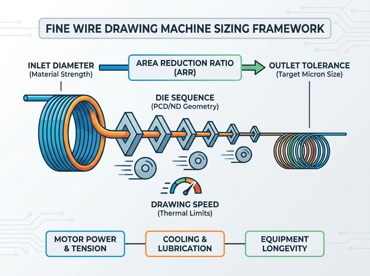
Die sequence architecture defines the mechanical heartbeat of the drafting process. Integrating a high-performance fine wire drawing system requires highly precise die material selection. You must assess Polycrystalline Diamond (PCD) versus Natural Diamond (ND) dies based on application. Material hardness and expected production volumes drive this specific choice. PCD offers exceptional durability and predictable wear rates for high-volume copper runs. ND provides superior surface finishes necessary for specialized ultrafine aerospace applications. Perform a strict cost-to-lifespan analysis to establish proactive die replacement schedules.
Drafting geometry plays a monumental role in controlling material flow. You must optimize the approach angle and the core reduction zone. For instance, softer materials like copper require different approach angles than harder alloys. The bearing length must also match your specific wire material to ensure dimensional stability. Evaluating die string alignment mechanisms is equally crucial for equipment longevity. Proper alignment minimizes lateral friction and prevents asymmetric die wear.
Finally, carefully evaluate slip versus non-slip machine configurations. Slip systems are incredibly common in multi-stage fine drawing environments. They allow controlled capstan slippage to naturally balance tension between drafting stages. Non-slip designs eliminate friction entirely but require complex, highly responsive motor synchronization. You must determine the best kinematic design for managing wire elongation safely. Consistent back-tension prevents catastrophic mid-run breaks and maintains wire linearity.
Operational speed aggressively influences both final product quality and machine longevity. Wire feeding speed dynamics dictate the internal material stresses generated during reduction. Inlet feeding speeds directly affect the yield strength and ductility of the wire. Sensitive materials like brass alloys and ultrafine copper react poorly to extreme velocity. You must identify the exact point of diminishing returns for your production line. Excessive speed increases cause hidden micro-fractures that compromise electrical conductivity. It also leads to severe surface scoring, rendering the wire useless for precision applications.
Maintaining high speeds requires exceptional thermal management and fluid engineering. Friction generates massive amounts of heat during rapid area reduction processes. You must evaluate the required cooling capacity carefully before scaling up production. Continuous, high-volume lubrication flow rates dissipate this dangerous friction heat effectively.
Assess the serious risks of lubricant breakdown at maximum operational speeds. Degraded lubrication destroys expensive dies and ruins wire surfaces almost immediately. Ensure your filtration system removes microscopic metal fines from the emulsion to prevent sludge buildup.
Common Material Speed and Thermal Considerations
Wire Material | Speed Sensitivity | Thermal Risk Factor | Recommended Lubrication Focus |
|---|---|---|---|
Ultrafine Copper | High | Moderate (highly ductile) | High-lubricity synthetic emulsions |
Brass Alloys | Very High | High (prone to embrittlement) | Heavy-duty boundary lubricants |
High-Carbon Steel | Moderate | Extreme (rapid heat generation) | High-cooling capacity mineral oils |
Selecting reliable fine wire drawing equipment requires strict, data-driven evaluation protocols. Drive systems and precision control sit at the absolute top of this list. Compare traditional AC motor setups directly with modern multi-axis servo drives. Servo systems offer superior tension synchronization across all interconnected drafting stages. Evaluate the responsiveness of the integrated PLC system meticulously. It must handle rapid acceleration and deceleration phases flawlessly to maintain tension. Poor PLC timing causes instant wire breakage during standard machine startup sequences.
Next, focus closely on capstan and drawing cone design specifications. Assess the surface treatment applied to the primary drawing cones. Tungsten carbide coatings and advanced ceramic rings offer exceptional wear resistance. You should analyze the physical footprint and frame thickness of the machine. Mechanical rigidity is necessary to dampen high-frequency vibrations during peak operation. Uncontrolled vibrations destroy micron-level outlet tolerances and shorten bearing life.
Energy efficiency metrics require deep scrutiny from engineering teams. Review actual power consumption metrics per kilogram of drawn wire. Do not blindly trust theoretical manufacturer claims found in standard brochures. Real-world power draw often exceeds baseline estimates significantly when pulling hard alloys.
Prioritize multi-axis servo drives for exact, repeatable tension control.
Verify the application quality of ceramic or tungsten carbide cone coatings.
Demand actual energy consumption data gathered from real production runs.
Check for integrated regenerative braking systems to recover electrical energy.
Avoiding common sizing pitfalls protects your capital investment and production timelines. Over-speccing machine capacity leads to massive, ongoing energy waste. The machine draws unnecessary power for standard, lightweight jobs, severely impacting profitability. Conversely, under-powering the equipment leads to severe motor strain and overheating. This causes frequent equipment downtime and guarantees missed production quotas. You must size the equipment exactly to your specific material and volume needs.
Rigorous validation and testing separate reliable vendors from poor ones. Buyers must demand verifiable material testing upfront before signing purchase orders. Insist on rigorous run-off trials at the manufacturer’s facility using your exact wire. You should never sign off before witnessing a successful, continuous test run. Ensure the vendor demonstrates consistent tension stability during these trials.
Finally, calculate your long-term Return on Investment (ROI) comprehensively. Factor in the long-term availability of proprietary spare parts and electronic components. Calculate your projected die maintenance costs accurately based on vendor data. You must also account for routine downtime during preventive maintenance cycles. Focusing purely on the initial purchase price is a critical, costly mistake. A cheaper machine with high downtime will destroy your operational margins rapidly.
Achieving perfect machine sizing demands a holistic evaluation of your entire production line. You cannot isolate single metrics like motor power or theoretical maximum speed. Instead, you must harmonize inlet limits, die geometry, and thermal management capabilities seamlessly. Manufacturers must recognize how drafting geometry and operational velocity directly impact material integrity.
Conduct a strict, data-driven audit of your current production bottlenecks.
Require prospective vendors to provide empirical operational data for their machinery.
Prioritize tension stability and thermal control over raw feeding velocity.
Establish a proactive maintenance schedule for dies and drawing capstans.
Take time to validate machine performance using your specific wire alloys. This careful approach guarantees high-yield production and long-term equipment reliability.
A: Excessive feeding speed increases friction and heat in the primary dies. This thermal spike can alter the grain structure of brass, leading to brittleness, surface defects, and a higher probability of wire breaks downstream.
A: Lifespan varies significantly by material (PCD vs. Natural Diamond), drawing speed, and lubrication quality. Buyers should track die wear by monitoring the gradual loss of outlet diameter tolerances rather than relying solely on operating hours.
A: The number of drafts is calculated by taking the total required cross-sectional area reduction (from inlet to outlet) and dividing it by the safe maximum reduction percentage allowable per draft for your specific alloy, ensuring the material's tensile limits are never exceeded.



 English
 简体中文


